


 1283 / 1588

ENGINE
84
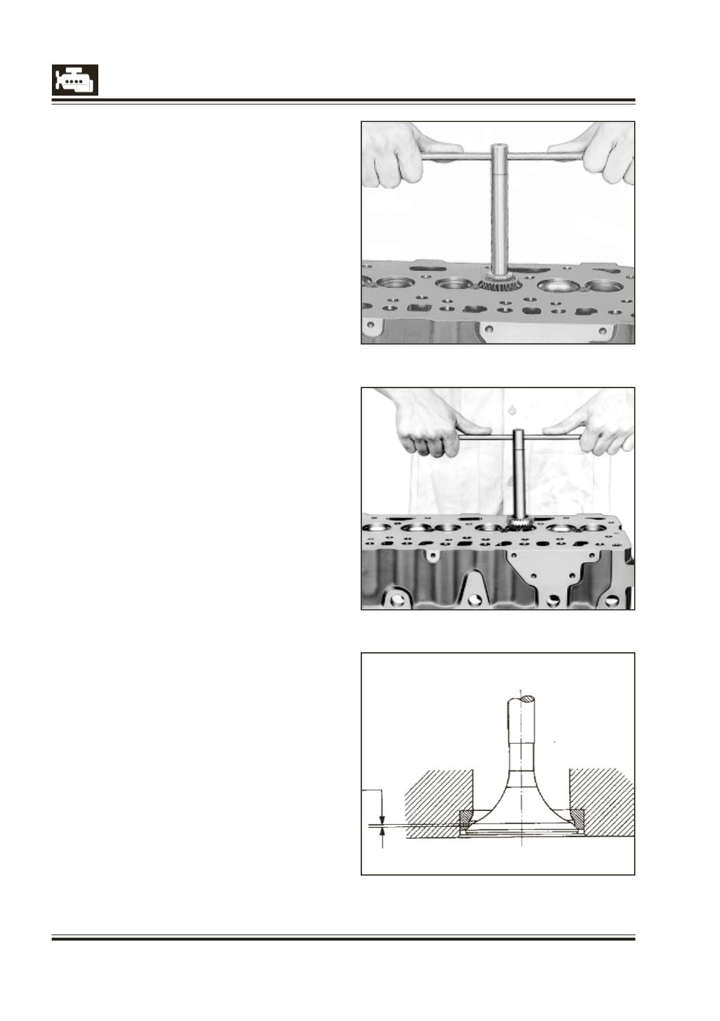
Fig. 6
0.5 mm
Fig. 4
Fig. 5
c. Check valve seat height with respect to cylinder
head parting surface. Replace valve seat inserts if
they are worn out beyond specified limit.
1 Place cylinder head on suitable wooden support.
2 Measure valve seat diameter.
3 Use 15 deg cutter for cutting exhaust valve seat
inserts as shown in Fig. 4.
4 Cut valve seats with a 45 deg cutter both for the
intake and exhaust inserts. Fig. 5.
NOTE
Seat must be absolutely faultless and without any
chatter mark.
5 If necessary, lap valve seats to a smooth and even
finish by using lapping paste.
6 Smear valve seat with carbon blue, place valve in
guide and turn it slowly under axial pressure. The
contact line on valve seat must be around the
entire circumference at equal width. The distance
between narrow diameter of valve seat to contact
line should be within specified limit. Fig. 6.
7 Check for leakage past valve and its seat by
pouring gasoline on valve head. The gasoline must
not seep past the seat.
8 Measure distance between valve head and
cylinder head parting surface. Refinish valve seats
if required.