


 1129 / 1588

58
GEAR BOX G-76
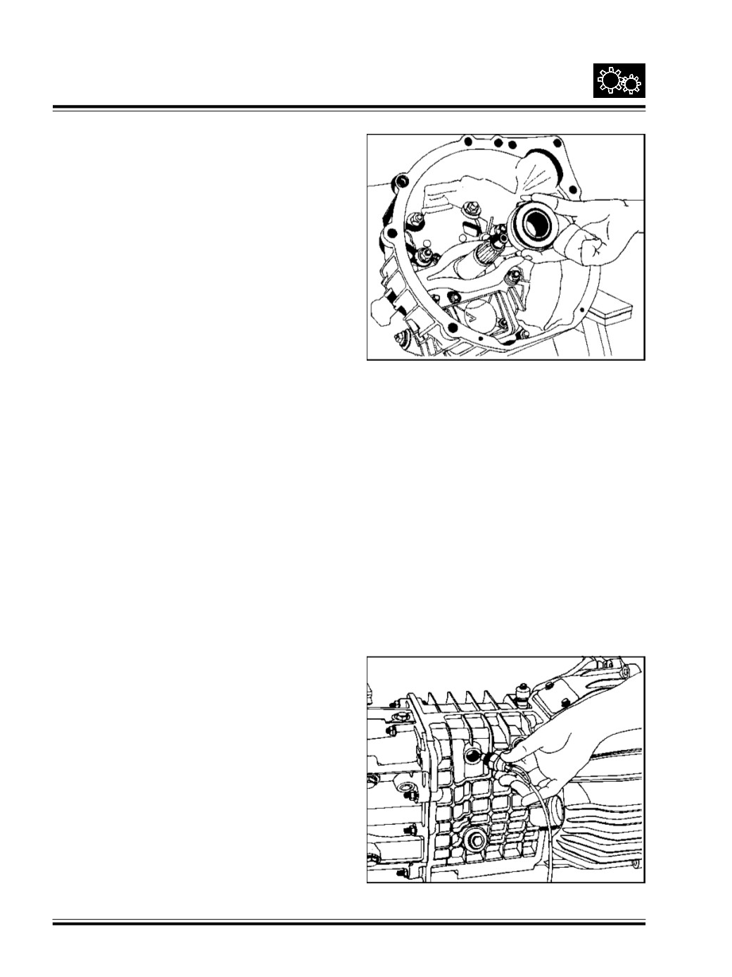
Fit clutch release bearing and release fork.
Ref Fig. 130
Fig. 130
Lift and mount the gear box at cylinder block face,
aligning drive shaft splines with clutch plate using a
dummy main shaft. Align the clutch plate to center
hub splines, first hand tight the diagonally opposite
bolts then tighten all the bolts to required torque. Clear
the gear shift lever through opening provided on the
cab.
Tighten all mounting bolts of clutch housing to required
torque.
Apply grease over supporting pin of extension armand
also inside rubber bush of extension arm support.
Slide support over pin.
Fit extension arm support on cross member.
Tighten nyloc nut alongwithwasher such as tomaintain
a clearance of 10 mm between extension arm stud
end and propeller shaft.
Fig. 131
Fit
-
Clutch slave cylinder and its piping.
-
Speedo cable
-
Reverse indicator switch connector Fig. 131
-
Propeller shaft
Fix rubber seal in its seat over tunnel cut out and over
plate, tighten screws along with washer.
Slide rubber bellow over collar of cover plate.