


 1101 / 1588

30
GEAR BOX G-76
15. DIS-ASSEMBLY OF GEAR CASE COVER-
FRONT
Remove oil seal with suitable punch.
Press out dowel pins, if required.
DISASSEMBLYOF GEAR CASE COVER – REAR
Remove main shaft oil seal from assy. gear case cover
rear with suitable drift.
Unscrew and remove assy. threaded plug. Remove oil
seal speedo shaft.
Pull out plug speedo drive. Press out shaft speedo
drive with suitable punch. Remove speedo drive gear.
Ref Fig. 62
Fig. 62
16. INSPECTION
Inspect inside of synchro cone for wear.
Inspect the synchro cone teeth and matching teeth
on gear for wear (rounded off). Ref fig. 63
Inspect the gear hub thrust surface for wear.
Inspect the cone surface for wear on 1st, 2nd, 3rd, 4th
& 5th main shaft gear; countershaft gears.
Inspect the teeth on all gears for uneven wear, scoring,
galling, and cracks.
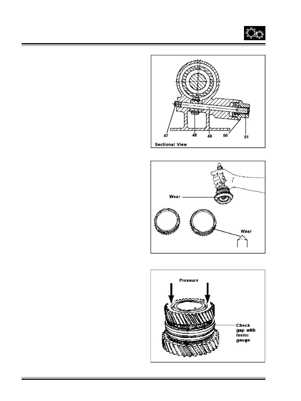
Place the synchro cone on matching gear cone and
rotate until it stops (approx. 10 to 20 degrees) then
measure the clearance between ring and gear. Ref
Fig. 64
Check for synchro cone gaps. It should be 1 + 0.3 mm.
Distance from rear cover outer wall to 3rd gear rear
side on counter shaft: 198 + 0.1 mm.
Distance from rear cover half outer wall to front end of
2nd gear on main shaft 197 + 0.1 mm.
Use sealing compound Maxi fixes s-758 Dunlop or
Duraplex 120 for sealing plugs.
Synchro Sleeve and Hub Inspection
Inspect the gear teeth on all synchro hubs and sleeves
for rounded off corners, indicating wear.
Install each hub in its mating sleeve and check for
freemovement.
Note: If replacement is required, always replace the
synchro sleeve and hub as a unit.
Fig. 63
Fig. 64