


 1033 / 1588

146
ENGINE2.2LDICOR
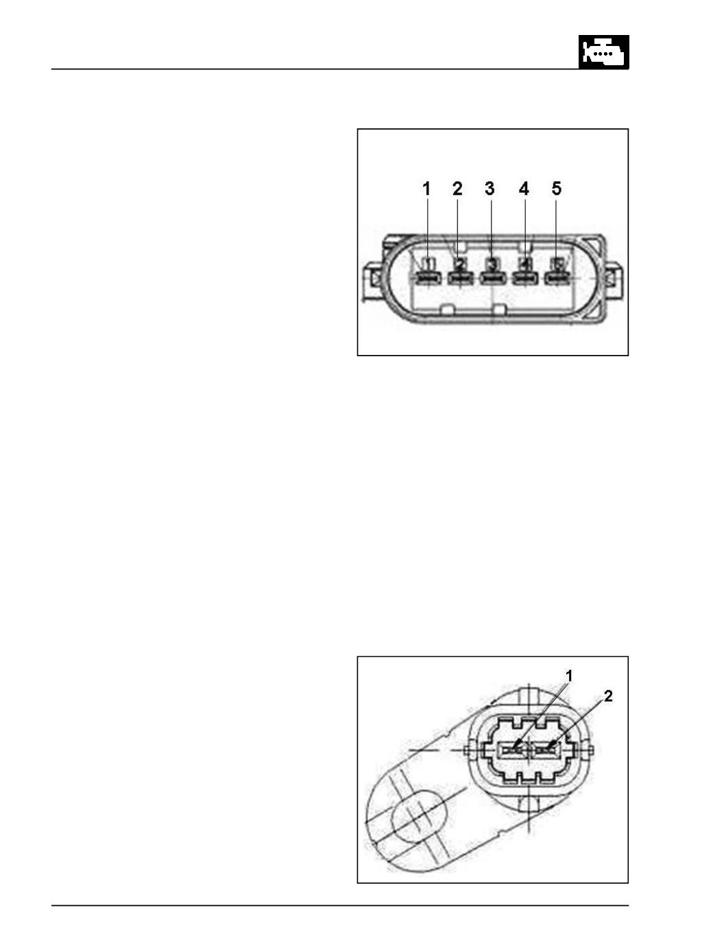
SIMAFSensor
(Fig. 243)
PinAssignment
Pin 1 :
+ Ub
Pin 2 :
Uext
Pin 3 :
MAFSignal
Pin 4 :
IAT+
Pin 5 :
GND/IAT-
CheckingCondition
l
With Ingnition 'ON',
l
Check Output Voltage between Pin 3 (MAF) and
Pin5 (GND).
l
Check Output Current between Pin 1 (Ub) and Pin
5(GND).
Signal/Output Current
The current consumption has to be between 35 and
55mA.
Signal/Output Voltage
The analog output signal is good between 0 and 1V
NOTE
Check theSIMAFSensor with nomass flow. The above
given values are for zero mass flow. Every tiny whiff of
air will cause a NTF".
Fig. 243
Fig. 244
Crank AngleSensor
(Fig. 244)
PinAssignment
Pin 1 - Positive terminal
Pin 2 - Negative terminal
CheckingCondition
Measure resistance across the terminals using Digital
multimeter.
Signal Output
Resistance spec : 2400 ohms ± 240@25
0
C.