


 1026 / 1588

139
ENGINE2.2LDICOR
EMSSensors
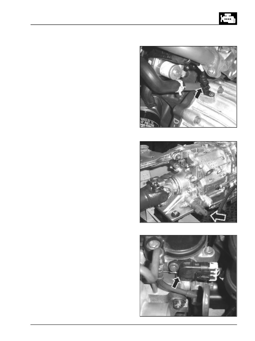
Fig. 224
Fig. 225
Fig. 226
1. CrankAngle sensor
(Fig. 224)
The crank angle sensor is fitted on the Clutch
Housing. The crank sensor is a magnetic field
sensitive transducer and generates a voltage
output proportional to the rate of change of the
magnetic field near a "Missing tooth"
configuration. It monitors the rotating speed
(rpm), the position of crankshaft/ piston and speed
fluctuations of the engine and gives continuous
feed back to the ECU. In other words it gives
engine speed and piston position signal to the
ECU. The sensor gap should be 1±0.5mm&should
be measured using feeler gauge. If the gap
between the flywheel and crank angle sensor is
not correct, the engine will not start.
2. VehicleSpeedSensor
(Fig. 225)
This sensor is located on the Transfer case / Gear
box based on the application which gives vehicle
speed information to theECU. It also helps theECU
in determining in which gear the vehicle is driving
and ensures smooth driving at all gears.
Note
In case of 4 x 4 Vehicles the VSS is located on transfer
case.
3. Camsensor
(Fig.226)
The cam sensor is fitted on the bearing frame. The
camsensor is amagnetic field sensitive transducer
and generates a voltage output proportional to
the rate of change of the magnetic field near a
"camshaft lobe" configuration. The cam sensor
senses the position of the flag on the Exhaust
camshaft and gives feed back to the ECU regarding
the cylinder No.1 (90ºBTDC). The sensor gap should
be 1±0.4mm.
If the gap is not correct and also the position of
camshafts with respect to crank shaft (set during
assembly), the engine will not start. While the
engine is running & the cam sensor fails then the
engine will continue to run till the engine will stop
& will not start again.