


 276 / 1231

ENGINE 1.3 QUADRAJET (75PS)
51
3A.1.2.3.4 ENGINE BLOCK – MEASUREMENT,
INSPECTION AND GRADE DETERMINATION
1. Clean sealant residues of f the mating surfaces
between: cylinder head extension/lower cylinder
head, upper crankcase/lower crankcase and
lower crankcase/crankcase sump.
2. Clean the parts removed thoroughly and check
their condition visually.
3. Fit the water/oil sealing plugs in the crankcase
using suitable fitting tools.
4. Lubricate all the mechanical component s with
engine oil.
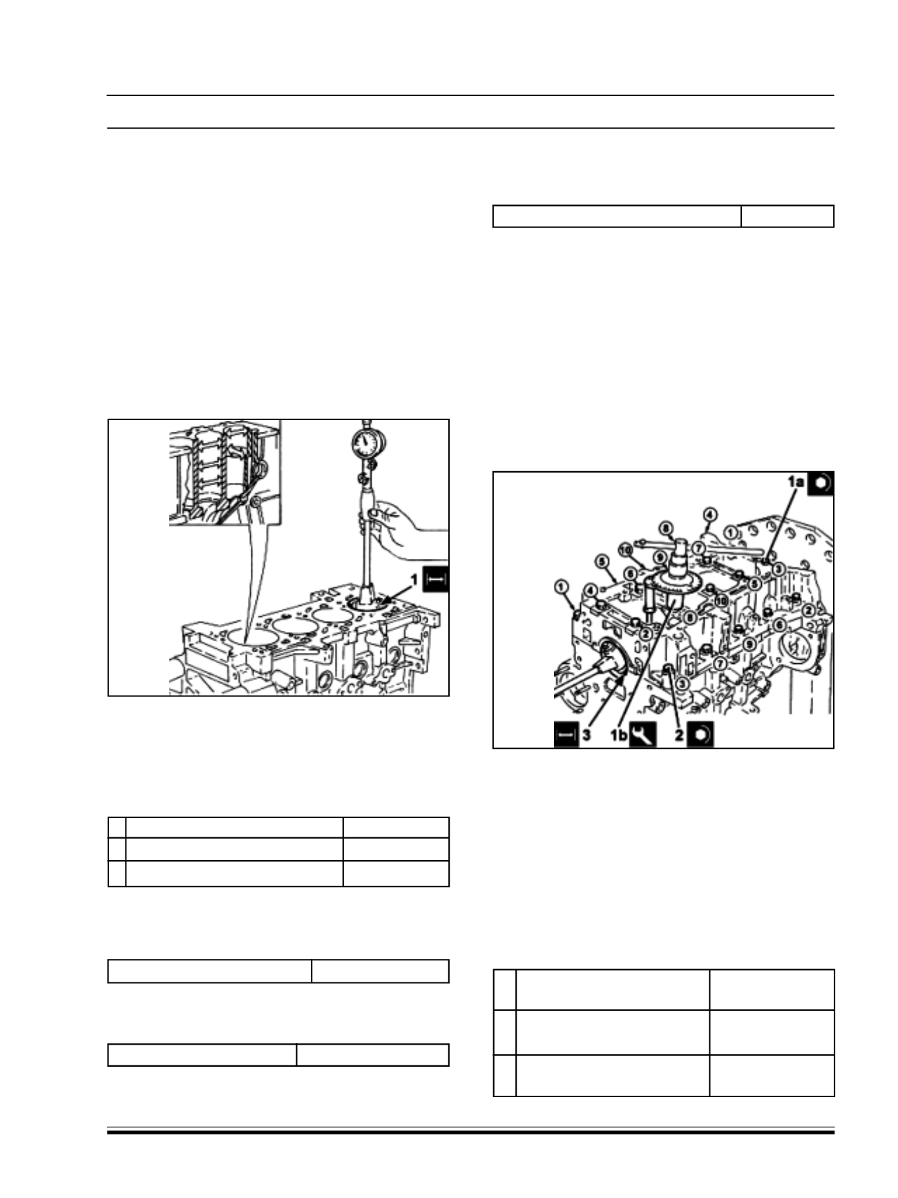
5. Measure the cylinder bore diameter using the
diagram illustrated.
6. Check for the values to be within the
recommended values for the respective grades
as shown below.
1 Cylinder liner diameter - Grade A (mm) 69.600 ~ 69.610
1 Cylinder liner diameter - Grade B (mm) 69.610 ~ 69.620
1 Cylinder liner diameter - Grade C (mm) 69.620 ~ 69.630
7. Check that the taper of the cylinder liners/bores is
within the recommended limit s of lesser than
0.010mm
Cylinder liner taper (mm)
< 0.010
8. Check that the ovality of the cylinder liners is within
the recommended limits.
Cylinder liner ovality (mm)
+/- 0.005
9. If the cylinder bore measurements are not within
the recommended limits, ream the cylinder bores
following the recommended oversize of 0.1mm.
Cylinder liner diameter oversize (mm)
0.1
NOTE :
If reaming is undertaken, ensure that all the bores
have the same oversize.
10 Use an appropriate support tool to replace the
upper crankcase on the overhaul stand.
11 Refit the lower crankcase locating bushes in their
seats.
12 Provisionally fit the lower engine block on the upper
engine block to measure the main journal seat s
and then remove it.
13.Loosen the central M10 bolt s (1a) securing the
lower crankcase to a torque of 1.9 ~ 2.1Kg-m +/-
3
0
, following the order shown in the figure. Use
the angular tightening tool (1b).
14.Tighten the lower crankcase side M8 bolt s to a
torque of 2.9 ~ 3.2 Kg-m, following the order shown
in the figure.
15.Check that the diameter of the main journal seats
is within specified limit s (without fitting the half-
bearings).
3
Main journal seat diameter -
Category A (mm)
54.710 ~ 54.714
3 Main journal seat diameter -
Category B (mm)
54.714 ~ 54.718
3 Main journal seat diameter -
Category C (mm)
54.718 ~ 54.722