


 546 / 1235

FRONT AXLE (4X4)
47
FRONT AXLE
(4X4)
Pin B and Chassis ground: Measured voltage = 0
Volts
Pin D and Chassis ground: Measured voltage =
Battery voltage (8 to 12 V)
Pin A and Chassis ground: Measured voltage = 4
to Battery voltage.
If the voltage is out of the above mentioned range,
check for any short circuits or open circuits. Recon-
nect the connector after rectifying the problem
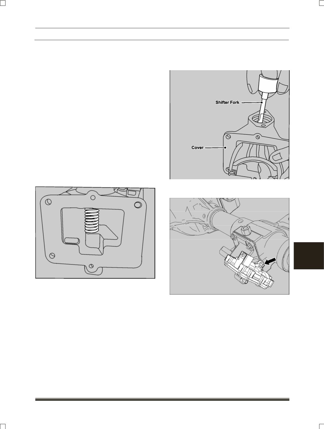
ASSEMBLY
1. Ensure cleanliness of disconnect housing cover,
shift fork, shaft shift fork and spring.
NOTE
Discard the old spring and use new at the time of
assembly.
2. Insert the spring and shift fork through the dis-
connect cover window while aligning the spring
into bore in the cover and sitting in the slit of shift
fork.
NOTE
Orientation of the shift fork is important and it should
be maintained properly.
3. Insert the shaft shift fork in the opposite way of
removal, ensuring that it passes through shift fork
as well as the spring. Press the shaft shift fork in
the bore by hand.
4. Install the electrical motor on cover assembly and
tighten the screw with specified torque.
NOTE
Ensure that the “O” ring on the electrical motor is not
cracked or damaged. If so replace the “O” ring.