


 542 / 1235

FRONT AXLE (4X4)
43
FRONT AXLE
(4X4)
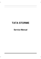
NOTE
Ensure uniform pressing of Knuckle into spindle
Does not rest spindle on wheel bolts; they may
slip out from the spindle during knuckle pressing.
Use machined face on spindle while pressing the
Knuckle into spindle
5. Lock the Spindle, Insert Correct CV Joint (i.e. as
per LH Side and RH side of the Knuckle). Install
the spindle nut and torque the same to specified
torque.
6. Install bolt cap and insert the cotter pin and bend
one of the pin leg
7. Install the shipping cap in 2 holes provided in
spindle to avoid contamination to enter into bear-
ing area.
CHECK AFTER WHEEL END ASSEMBLY
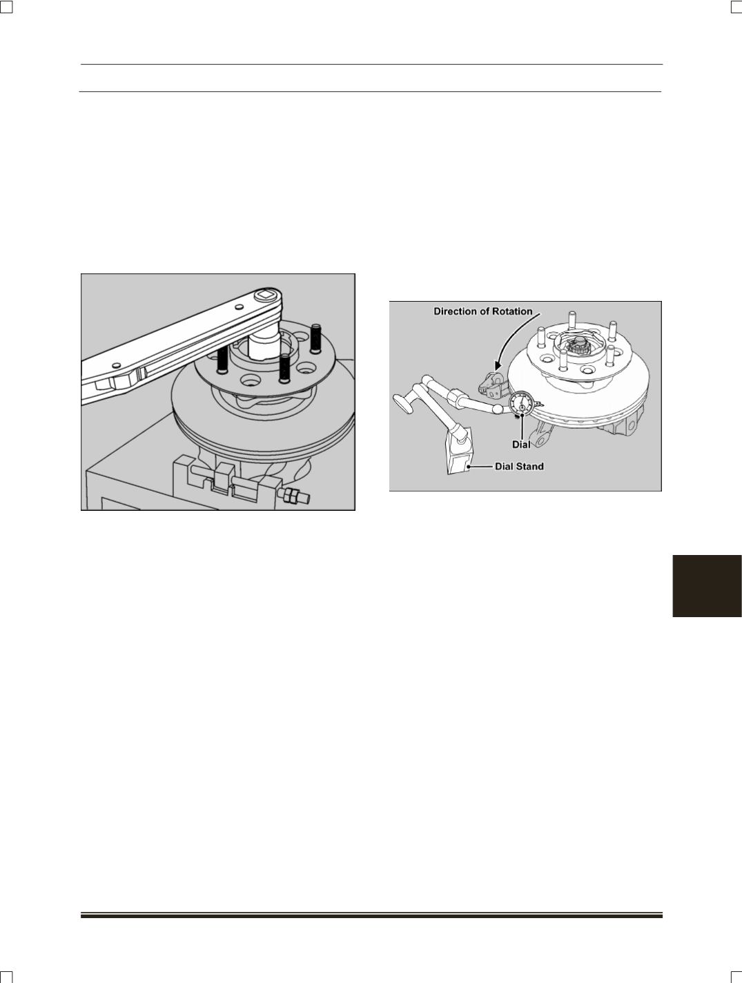
MEASUREMENT PROCEDURE FOR BRAKE DISC
RUNOUT OF FRONT AXLE ASSEMBLY
Following method is adapted to measure the brake
disc run out on wheel end assembly
(LH and RH
Side)
of Front Axle Assembly.
1. Attach the dial indicator on the base stand on
which wheel end assembly is securely mounted.
2. Adjust the dial stand in such a way that the direc-
tion of the tip of dial indicator is parallel to
direction of the movement of the brake disc while
checking run out.
3. Ensure that brake disc surface is clean and dial
indicator tip touching to brake disc on circle of Di-
ameter ≈ 280mm from wheel end centre line.
4. Rotate the brake disc while watching the dial indi-
cator needle movement; record the maximum
value shown on the dial indicator. This value
equals to brake disc run out.
5. The brake disc run out need to be maintained up
to 0.130 mm
(130 Microns)
max with the above
mentioned procedure.
NOTE
Refer Brakes group for further details on Disc In-
spection and repairs.