


 527 / 1235

FRONT AXLE (4X4)
28
INSPECTION
a) Inspect gear teeth of side gears and pinion mate
gears for wear and cracks.
b) Inspect external teeth of side gears for wear and
cracks.
NOTE
If replacement of one gear is required, then BOTH
side gears, pinion mate gears and washers have to
be replaced.
c) Inspect cross pin for excessive wear. Replace if
necessary.
NOTE
Always replace gears as a complete set. Do not mix
new gears with old gears, as this may cause uneven
wear and short gear life.
RING GEAR and PINION ASSEMBLY THEORY:
1. Ring gear and pinion is supplied as a set. They
are matched with each other during manufacture.
Matching numbers on both pinion and ring gear
are etched for verification. Refer Fig A and B
given below:
2. If a new gear set is used, verify numbers on pin-
ion and ring for matching before proceeding with
assembly.
3. Standard mounting distance from center line of
ring gear to back face of pinion is 103.5 ± 0.1
mm. This dimension is controlled by selecting
shims, which are positioned between the inner
pinion bearing cone and pinion gear. Best running
position of gear set is achieved by proper shim
selection.
4. This dimension for front live axle will be different.
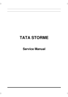
On the bottom face of pinion, number is etched. It
can be a plus (+) number, a minus (-) number or
Zero (0). Required pinion shim selection is
achieved with help of this number. If alphabet "m"
appears on pinion face shim, selection has to be
done in mm (Metric). If alphabet "m" does not ap-
pear on pinion face, shim selection has to be
done in inches.
5. Shims with different thicknesses are available for
selection.
Use tables on next page as a guide for selecting
correct thickness of shims either for addition or
for subtraction from old shim pack.
Refer figure A which shows ring and pinion
etched with inch identification. Refer Table A.
Fig: A
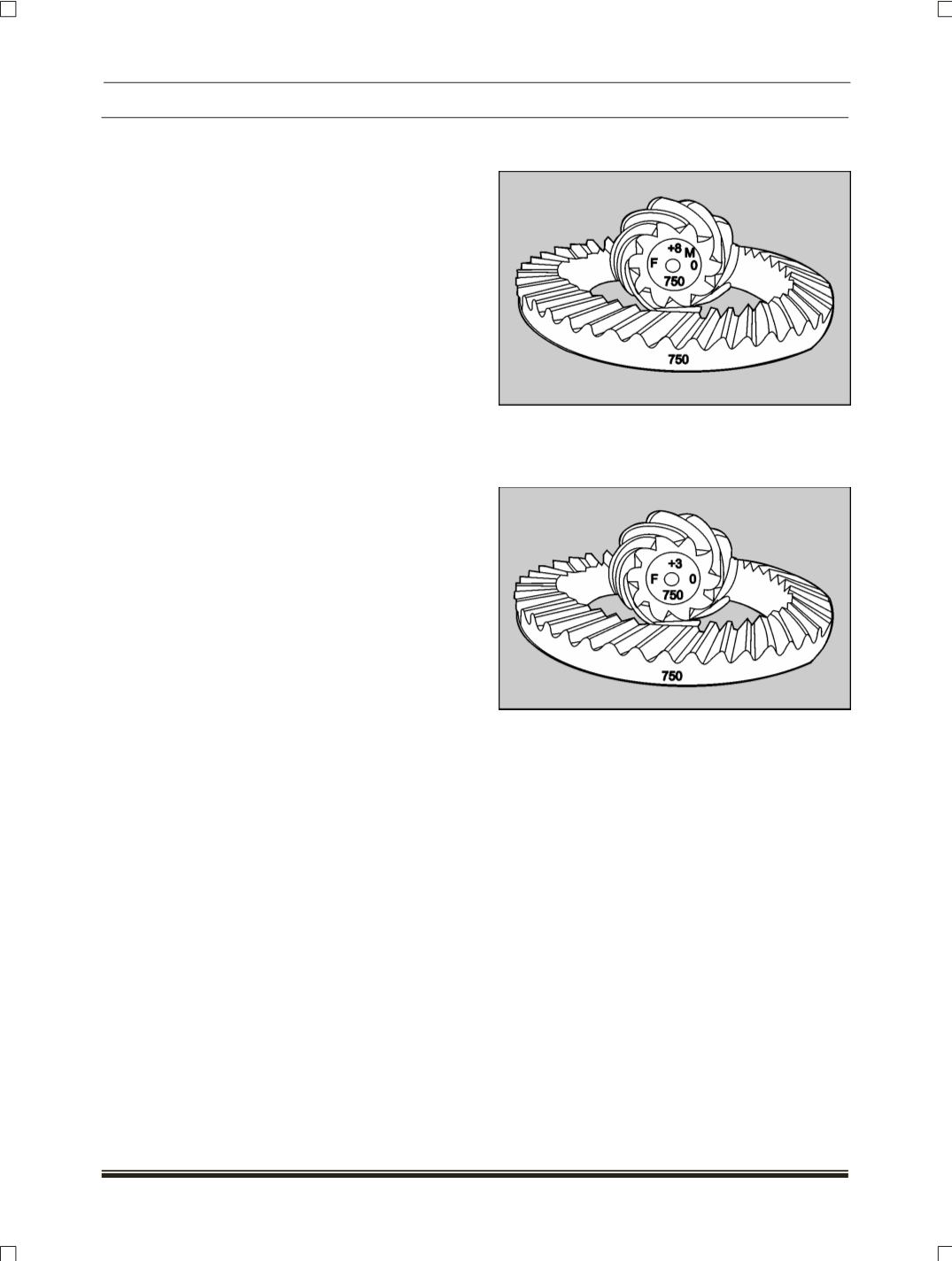
Refer figure B shows ring and pinion etched with
metric identification. Refer Table B.
F
ig: B