


 218 / 1428

212
ENGINE 273 MPFI
Components of Evaporative Emission Control
System
Roll Over Valve in built with Fuel Module (Refer Fuel
Module)
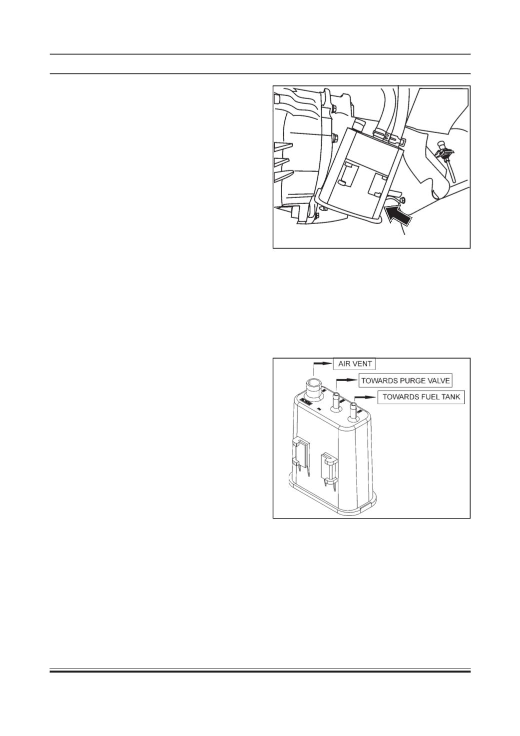
Carbon Canister
A canister made of high grade Nylon, containing spe-
cial dust free activated carbon is used to absorb fuel
vapours. The upper end of the canister is open to at-
mosphere for ventilation. The end is not really open
but there is foam filter. The purpose of the bottom filter
is to protect the canister from dust and dirt during
operation.
EVAPORATIVE EMISSION CONTROL
SYSTEM
Objective
The car is fitted with an evaporative system to meet
all requirements of evaporative emission.
The system is designed to prevent fuel vapours formed
within the tank and fuel system from escaping into
the atmosphere.
General Operation Of Evaporative Emission Con-
trol System
The system operates when atmospheric temperature
is higher, after the vehicle has been parked / standstill
for a long time; the fuel temperature rises and brings
about a pressure rise inside the tank. This rise may
occur with medium - low fuel levels or with the tank full
condition during tank refilling, the pressure inside is
more or less same as atmosphere pressure. The
breather port on fuel tank is connected to the filler
neck which allows tank breathing during fuel filling.
When the fuel filler cap is closed, it seals the system,
the vapours generated inside the tank (with vehicle
moving or while parked) due to fuel volatility, tank in-
ternal pressure builds up until the rollover valve open-
ing level is exceeded. When the engine is inoperative,
(i.e. while parked), fuel vapour generated inside the
fuel tank due to fuel volatility are absorbed and stored
in the canister. When the engine is running, the fuel
vapours get absorbed in the canister after which they
are purged into the intake manifold through canister
purge valve operated by the ECU.
Removal & Fitment:
1. Disconnect hoses from canister to purge valve.
2. When the air is blown into tank port, there should
be no restriction of flow through purge port andAir
port.
3. If the operation differs from the above description,
canister must be replaced.
4. Connect hoses to canister.
5. Ensure that hoses are clamped securely.
When the engine is inoperative (i.e. while parked) fuel
vapours generated inside the fuel tank due to fuel vola-
tility are absorbed and stored in the canister through
tank pressure valve. When the engine is running, the
fuel vapours absorbed in the canister are purged into
intake manifold through canister purge valve operated
by ECU. The purging takes place due to air drawn
through the canister because of pressure differential
between manifold vacuum and atmosphere.