


 376 / 896

TRANSAXLE-AMT
49
5. Seal the ‘Transmission Control Unit’ in correct
ESD compliant bag closed by thermal welding
and containing Silica Gel unit (for humidity
absorbability).
6. Place the ‘Transmission Control Unit’ in an
ESD proof package designed to protect
connections, sensors and gasket from
accidental contact.
7. Always protect ‘Transmission Control Unit’
from exposition to water, humidity or other
foreign materials (‘Transmission Control Unit’
is water/humidity proof only when mounted on
the system).
8. The ‘Transmission Control Unit’ package must
ensure protection against the accidental fall of
tools or other pieces, in particular on the
connectors and sensors.
9. Never
use improper tool (screwdrivers, etc.) to
lift and extract the ‘Transmission Control Unit’
from the electro valve block.
10. The surface of the electro valve block must be
absolutely
clean and free from oil or other
polluting substances.
Removal:
NOTE
Any extraction tool (if any) that will be developed
must be submitted to ‘MAGNETI MARELLI’
approval.
1. Disengage the female connectors with the
cables from the ‘Transmission Control Unit’.
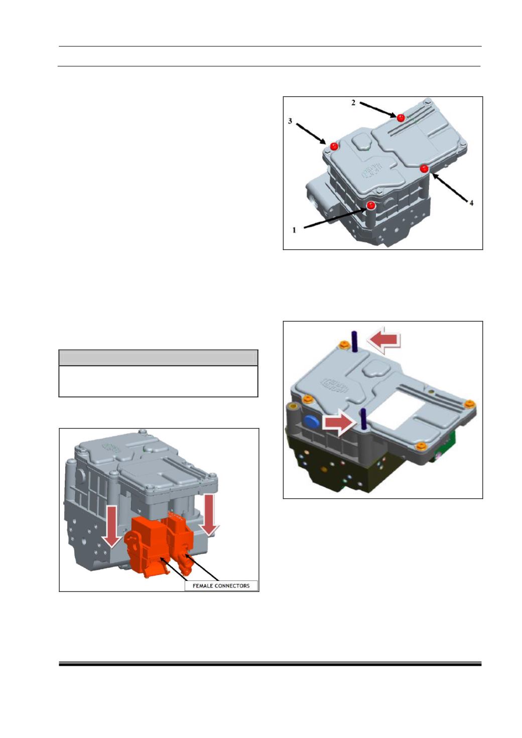
2. Unscrew the four ‘Transmission Control Unit’
fixing screws with sequence indicated below.
3. In order to guarantee right ‘Transmission
Control
Unit’
translation
during
the
dismounting, screw two 100 mm. length M5
threaded rods in the holes previously used by
‘Transmission Control Unit’ fixing screws and
shown in the picture below.
4. Disconnect the right ‘Transmission Control
Unit’ from the electro valve block (disinsertion
of all the electro valves, pressure sensor and
ground
tabs)
with
appropriate
load
precautions. The operation must be
guaranteed by a ‘Transmission Control Unit’
translation of 90 mm (Min.) in the vertical axis
direction guided by the two threaded rods (see
image below).