


 465 / 1006

SUSPENSION SYSTEM
459
SUSPENSION
SEMI-TRAILING ARM
NOTE:
Refer exploded view of Rear Suspension
Components for removal and installation process
Removal
1. Remove wheel(s) (Refer wheel removal procedure/
Wheels and Tires group)
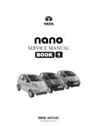
2. Remove wheel hub cover (c), wheel lock nut (b)
and thrust washer (a) .
NOTE:
Before loosening a coupling nut, attach a
transparent (vinyl) bleed tube to the bleed screw and
loosen the same to 3/4th turn. Pump out the brake
fluid in a suitable container by operating the brake
pedal.
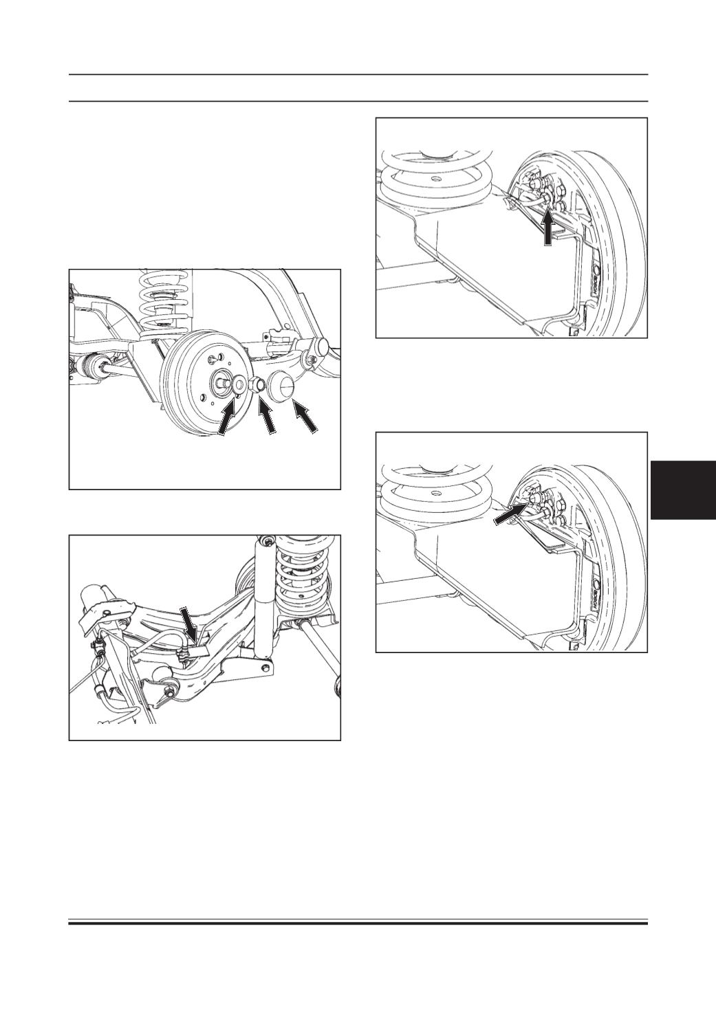
3. Remove the brake hose clip mounted on the semi
trailing.
4. Unscrew the brake line coupling nut.
c b
a
5. Support the semi trailing (01) arm (as shown below
by arrow in fig. given below) so that:
(a) It will keep the semi trailing arm from flying
downward when the shock absorber is unbolted.
(b) Drive shaft angles are not exceeded.