


 214 / 1006

208
ENGINE 273 MPFI
•
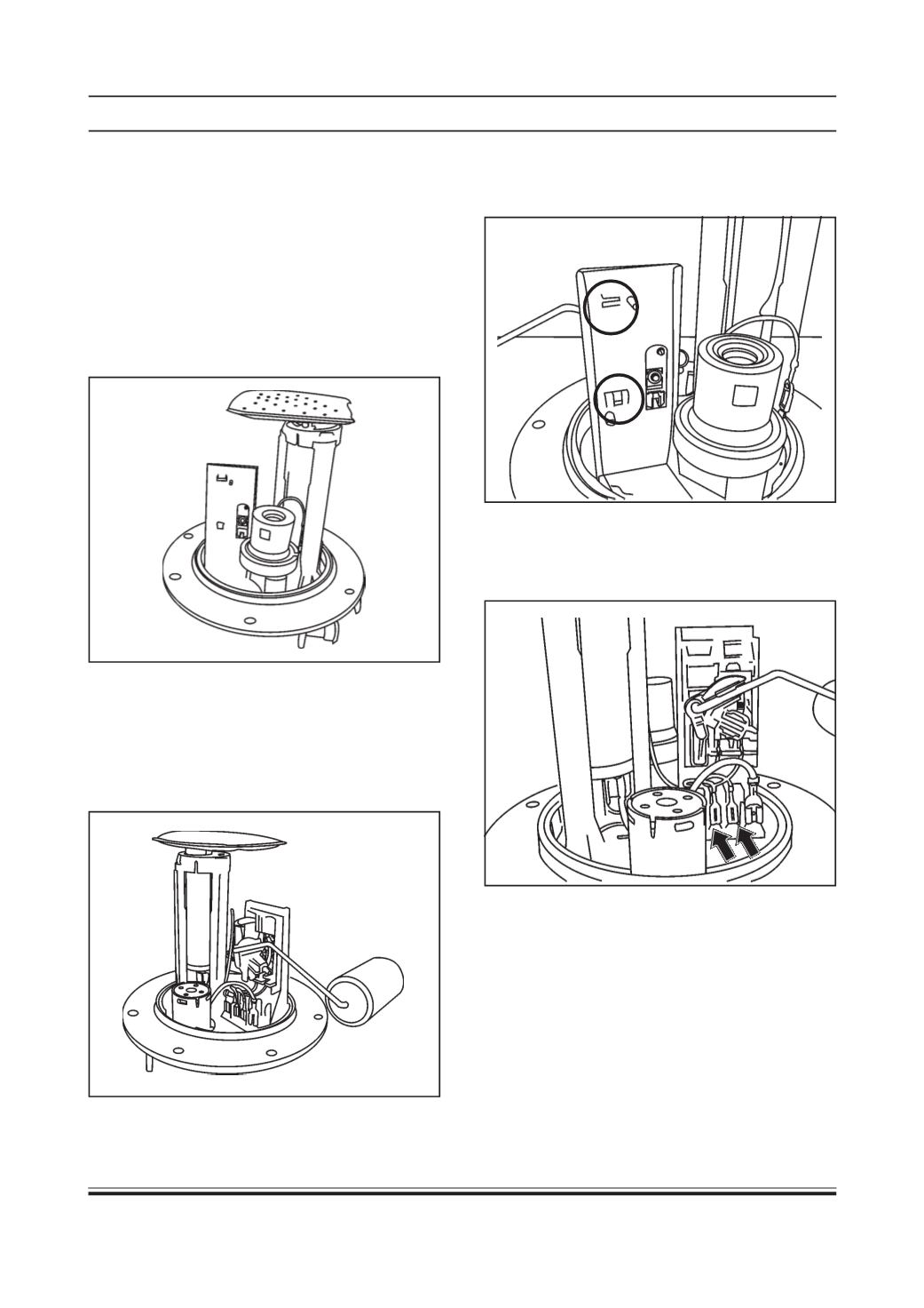
Take out the new pre-calibrated Level Sensor
Assembly from the cover.
•
Assemble the new pre- calibrated Level Sensor
Assembly with the assistance of two locating pins
provided on Level SensorAssembly and themating
guiding holes provided on the Flange.
•
Press the new pre- calibrated Level Sensor
Assembly unit you hear the click sound of clips
being locked. Visually confirm clipping on flange
•
Reconnect the electrical connector of the Level
Sensor Assembly. Ensure that blue wire is
connected to S+ and black wire is connected to
S- terminal.
Assembly procedure
:
NOTE:
•
Spare level sensor assembly does not require cali-
bration since it is precalibrated with master flange.
•
Do not handle the spare level sensor assembly by
lever float assembly since it might lead to distur-
bance in calibration values due to any changes in
the bend angles of the lever.
•
Hold the dissembled Level sensor Assembly Fuel
Supply Unit upside down.
Clip B
Clip A