


 718 / 1904

706
ELECTRICAL
Ground points
Ground points are identified with an eyelet symbol and
a connector number, except where components are
grounded through its fixings, when only the eyelet
is shown.
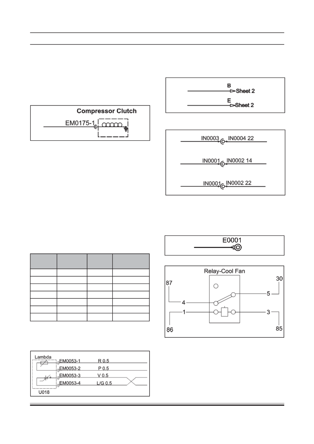
Relay Identification:
In this manual relay pin nos. are different from the DIN
standards relay pin nos. so please read the pin no as
follows:
Pin 1 – Pin 86
Pin 3 – Pin 85
Pin 4 – Pin 87
Pin 5 – Pin 30
8.20.2 UNDERSTANDING THE CIRCUIT
DIAGRAM:
COMPONENTS
Each component has a description i.e. Compressor
clutch
NOTE:
Adotted outline indicates that the component
identified is not shown in its entirety.
Connectors
Connectors are identified by their corresponding
connector number with a numbered suffix to indicate
the pin-out detail of the wire, i.e. EM0175-1
identifies Harness EM (EMS or Engine), 0175 the
connector no.& pin number 1 .
Wire Identification
There are two kinds of coloured wire used in this
vehicle. One is single coloured wire & other is dual
coloured (striped) wire. The single coloured wire uses
only one colour symbol (i.e. “G”). The dual coloured
wires uses two colour symbols (i.e. G/Y) The first
symbol represents the base colour of the wire (i.e. “G”
& second symbol represents the colour of the strip
(i.e. “Y”) The wire is identified by its colour and its
CSA (Cross sectional area ie 0.5 = 0.5 CSA).
SYMBOL WIRE SYMBOL WIRE
COLOUR
COLOUR
B
BLACK
P
PINK
BR BROWN R
RED
G GREEN WH WHITE
GY GRAY
Y
YELLOW
L
BLUE
LG LIGHTGREEN
O ORANGE V
VIOLET
SB SKY BLUE
The arrows illustrated below show an example of the
page break symbols, identifying that the circuit
continues at the corresponding letter on the sheet
number indicated.
The cup and ball symbol represents the male and
female halves of connector
Line Types
Crossed wires as illustrated below show an example
of how a twisted pair of wires may be represented on
the circuits.