


 1359 / 1904

FUEL SYSTEM
20
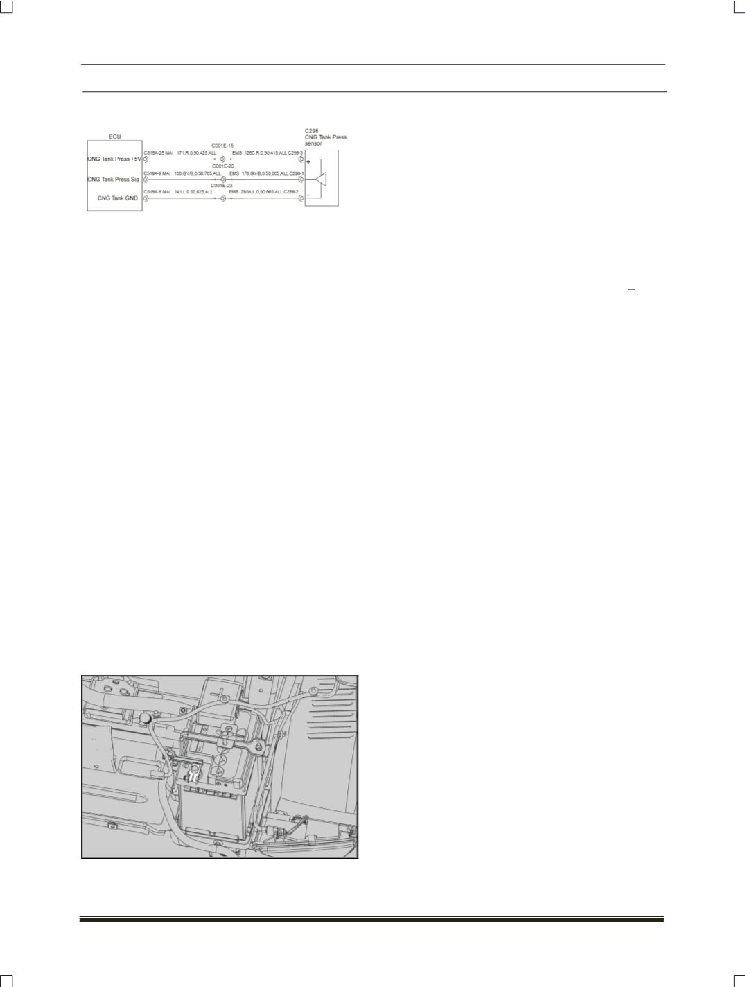
Wiring details (ECU & Sensor):
Stand Alone Diagnosis:
(At NTP conditions)
By using Multimeter:
Output voltage (between pin 1 & 2):
Approx 0.5 VDC at 1 bar G
Approx 3.6 VDC at 200 bar G
Use TATA Diagnostic Tool & perform actuator test.
REMOVAL OF H.P SENSOR FROM PRESSURE
REGULATOR (On vehicle):
NOTE
Park the vehicle with brakes ON and duel
selector switch is kept in CNG mode.
Manually turn of the tank valve and connect
the TML tester tool and start the service
“Empty CNG lines”
Crank the engine and run in idle condition
until engine stop at its own.
Re crank the engine it should not start (tank
pressure should be 0 bar)
WARNING :
Do not turn OFF Cylinder Valves , in vehicle
running in CNG mode. This may wrongly detect
the leakage error.
Disconnect. Battery negative cable.
Disconnect Solenoid valve connection.
Disconnect electrical connection of HP sensor
Remove the HP sensor by using 27 metric.
Wrench.
RE-FITMENT OF H.P SENSOR ON PRESSURE
REGULATOR (On vehicle):
Before installing the sensor, always ensure
good condition of the “O” ring.
Refit the H.P sensor on pressure regulator.
Tighten the H.P sensor to a torque of 50 + 5 Nm
(Note: Apply torque only at the hexagonal area).
Do a leak check after fitment.