


 1314 / 1904

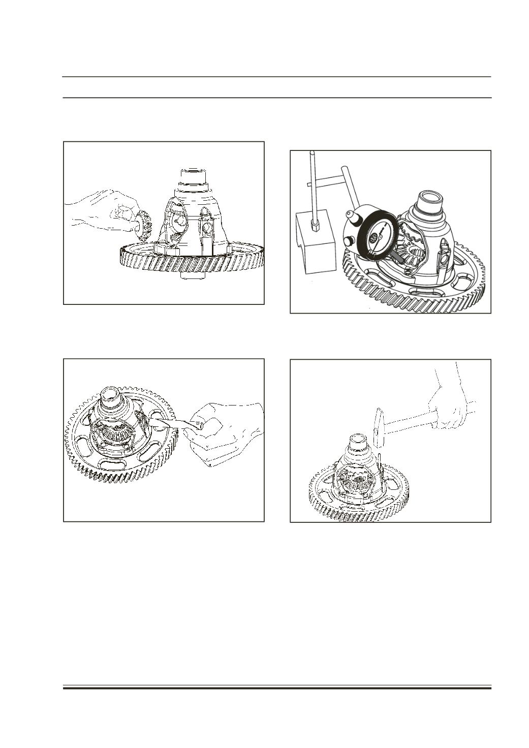
5. Inser
cage
6. Inser
the b
spide
Note:
•
Beve
as a
•
Make
rotat
t the two bev
.
t the spider th
evel pinions
r is aligned
l gears and b
set only and
sure that th
ing.
el pinions o
rough the ca
. Make sure
with the slot
evel pinions a
not individua
e Bevel gea
n either side
ge and then t
that the slo
in the cage.
re interchan
lly.
rs and pinio
s of the
hrough
t in the
geable
ns are
7. Measure
be within
varying
8. Insert th
cage.
the backlas
0.0 ~ 0.1 m
the bevel gea
e dowel sle
DRI
h using a dia
m. Backlash
r washers.
eve, to lock t
VETRA
l gauge; it sho
can be adjus
he spider to
IN
45
uld
ted
the