


 265 / 1575

CLUTCH
20
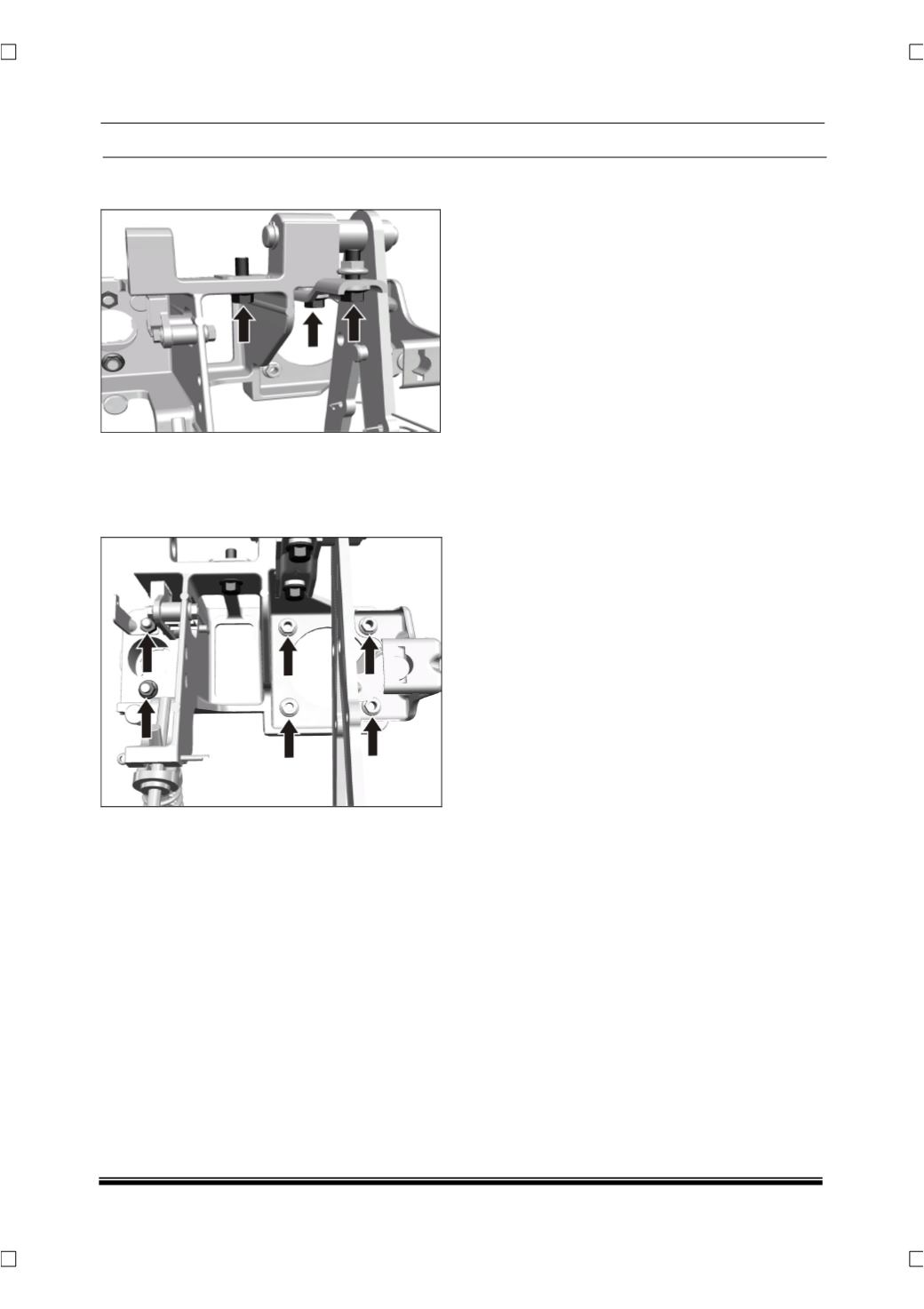
9. Remove 'Z' bracket and CCB Support bracket
bolt.
10. Ensure that all the mounting nuts and allen
screw are removed from the control bracket
and then take out the control bracket with
clutch and brake pedal assembly from the
vehicle
.
11. Individually remove the clutch pedal and brake
pedal from the control bracket. (For procedure
refer Clutch pedal assembly removal from this
section and brake pedal removal from brake
section.
INSPECTION
1. Check the clutch pedal for distortion or bending.
2. Check the return spring for damage or
deterioration.
3. Check the rubber cover of pedal plate for
damage or wear.
4. Check the clutch pedal lateral play. (Before
Dismantling)
FITMENT
For fitment follow the reverse procedure of
removal.
NOTE
•
While assembling refer the stay rod assembly
procedure & caution.
NOTE
•
No clutch pedal play adjustment is required as
this vehicle is fitted with Hydraulic System.
•
At the time of assembly apply thin coat of
grease (Grease 3% MoS2, SS: 6820-320,
TS:2520PI) on clevis pin.
•
Align the axis of clutch pedal hole with the
Clutch master cylinder (CMC) fork hole and
after inserting the clevis pin through Clutch
master cylinder (CMC) fork and clutch pedal
check the free rotation of clevis pin.
•
While putting back the stay rod along with the
compression spring apply thin coat of grease
(Grease 3% MoS2, SS: 6820-320, TS:2520PI)
at the tip of the pivot pin in order to reduce
friction.
•
Ensure the clutch pedal bush is fitted at the
time of assembly.
•
NEVER bleed the CSC if the clutch and
flywheel are not yet assembled.