


 678 / 745

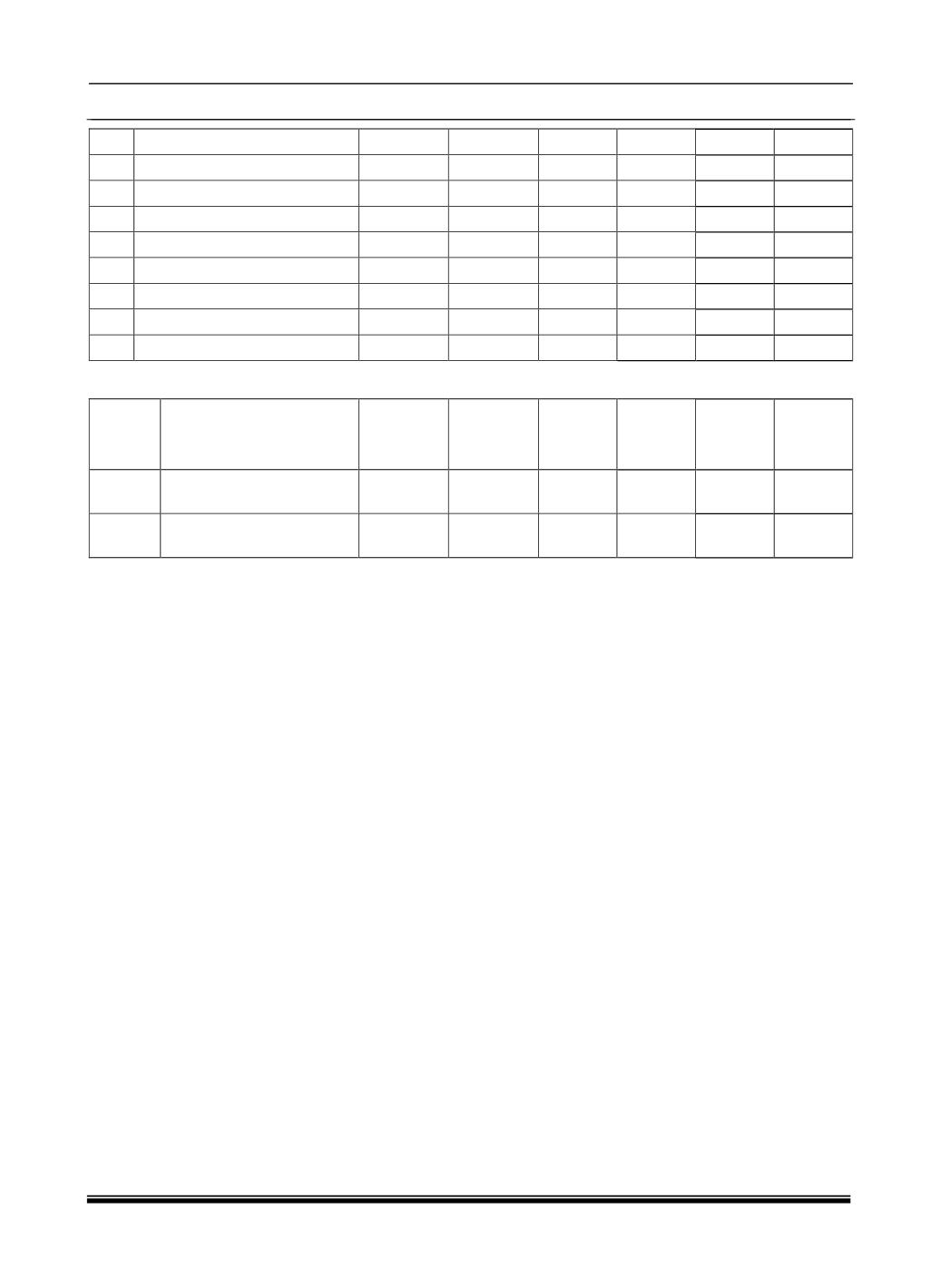
ELECTRICAL
36
24
Spare Digital Input3
Digital
Input
NA
NA
NA
NA
25
Can H (Diagnostic)
Bus
Bus
NA
Y
Y
Y
26
Can L (Diagnostic)
Bus
Bus
NA
Y
Y
Y
27
Spare PWM Output
PWM
Output
High/low NA
Spare
Spare
28
Wake up input
Digital
Input
High
NA
PP
PP
29
PRND Output
PWM
Output
High/low Y
Y
Y
30
Common IP Dimming output PWM
Output
LSD
Y
NA
Y
31
Sport Mode Output
Digital
Output
Low
NA
Y
Y
32
Spare PWM output 2
PWM
Output
LSD
NA
PP
PP
FAKRA CONNECTOR
SR.NODESCRIPTION
TYPE OF
INPUT
INPUT
/OUTPUT
ACTIVE
LEVEL/
STATE
DIAGN-
OASTIC
Low
end
High
End
Center Cluster Display Serialized
input
Digital
Input
NA
NA
NA
Y
Shield
Cluster Display signal
input shield ground
Power
Ground
NA
NA
NA
Y
NA-Not applicable, PP- Package protected, Y- applicable.