


 470 / 745

HVAC
18
7. FRONT HVAC UNIT
The front HVAC unit in vehicle comprises of the fol-
lowing parts:
i) BLOWER.
ii) BLOWER RESISTOR
iii) EVAPORATOR COIL AND TXV
(THERMAL
EXPANSION VALVE)
iv) HEATER COIL
i) BLOWER:-
The Blower is located at the top on the backside of
HVAC unit when viewed from inside the vehicle. It
acts as a centrifugal pump drawing in air from the
center and pushing it out diagonally. The air flows
through the evaporator and the heater coil and then
to the cabin.
The Blower speed is controlled using a blower con-
trol module.
Blower Motor Specification
MAKE
HYOSUNG
VOLTAGE
DC 12.5 V
CURRENT
25A 10% MAX
RATING TORQUE 0.56 Nm @12.5 V
RATING SPEED
3800 ± 300 rpm
RATING OUTPUT 313 W MAX
AIR FLOW
545 M3/HR
CLAMPING TORQUE TBD Nm
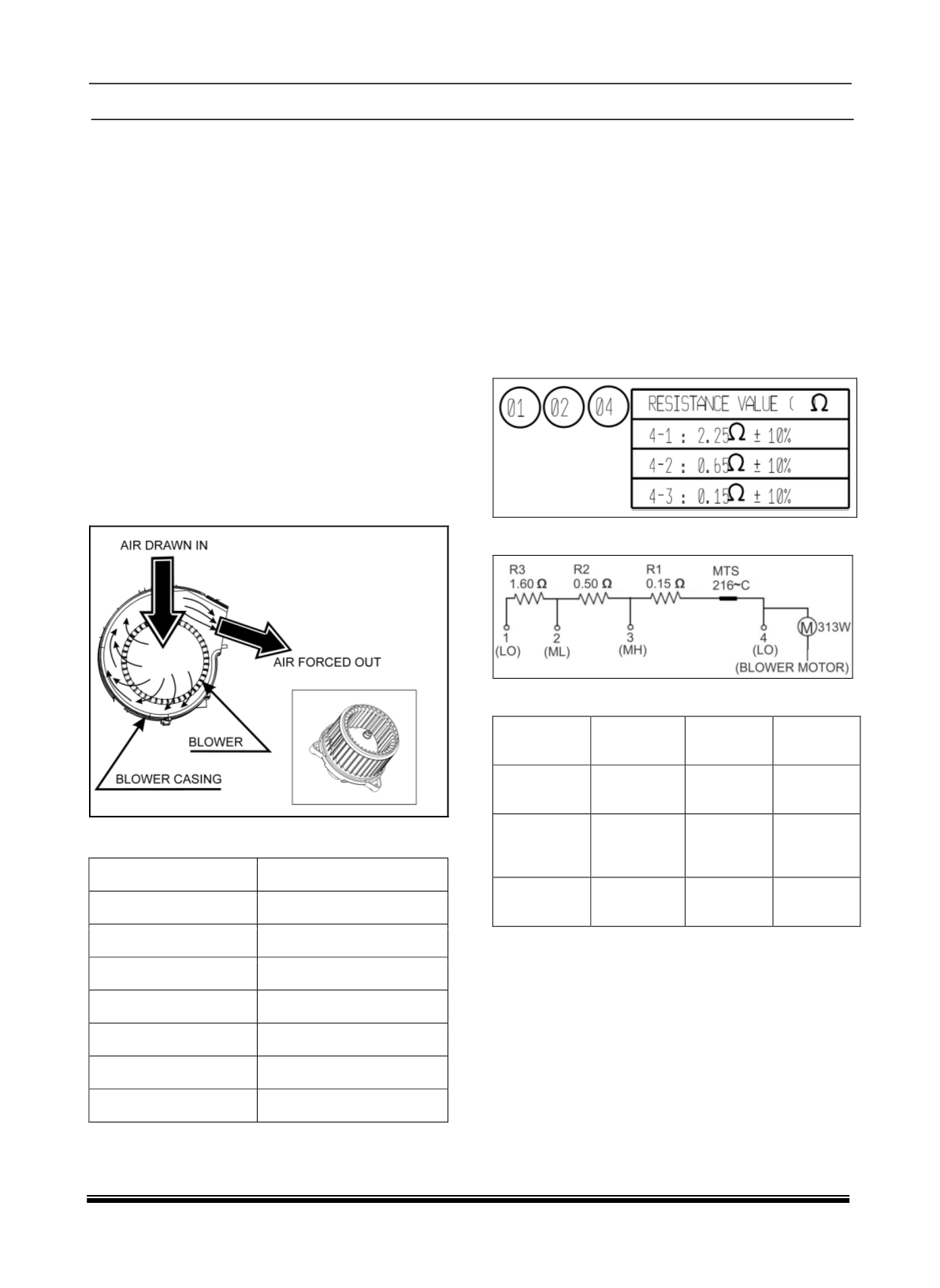
ii) BLOWER RESISTOR
The speed of the blower can be controlled by em-
ploying either a Blower resister. The blower resist-
er is used in models with manual HVAC.
A blower resister used is for a four-speed control of
blower speed. This is achieved by having a combina-
tion of three different resistances. The blower resist-
er is placed in the intake air flow to allow it to
dissipate heat freely.
Resistance Value in Ω
CIRCUIT DIAGRAM
Resistance Specification:
RESISTANCE
VALUE
R1
0.15±10% Ω
R2
0.15±10% Ω
R1
0.15±10% Ω
WIRE
DIA.(MM)
1.0
0.61
0.51
WIRE
LENGTH
(MM)
360±15 mm
310±15 mm 375±15 mm
NUMBER OF
TURNS
4.5±1
3.5±1
4.5±1