


 89 / 801

LV ELECTRICAL SYSTEM
3
carefully. Improper contact pressure between
mating terminals disturbs the connectivity
between them. Replace the damaged
connector body to avoid exposure of the
terminals in case of inadequate contact
pressure.
Ensure proper connection between the
terminals to the wire. Rectify the loose
connection by repairing / replacing the wire
harness. Worn out insulation of the wire may
result in short circuit. Avoid water entering in
the connectors.
10.Before removing a faulty component, refer to the
Workshop Manual for removal procedures.
Ensure the ignition is turned to the ’OFF’
position, the battery is disconnected and any
disconnected harnesses are supported to avoid
any undue strain at terminals. When replacing
the component keep oily hands away from
electrical connection areas and push
connector’s home until any locking tabs fully
engage.
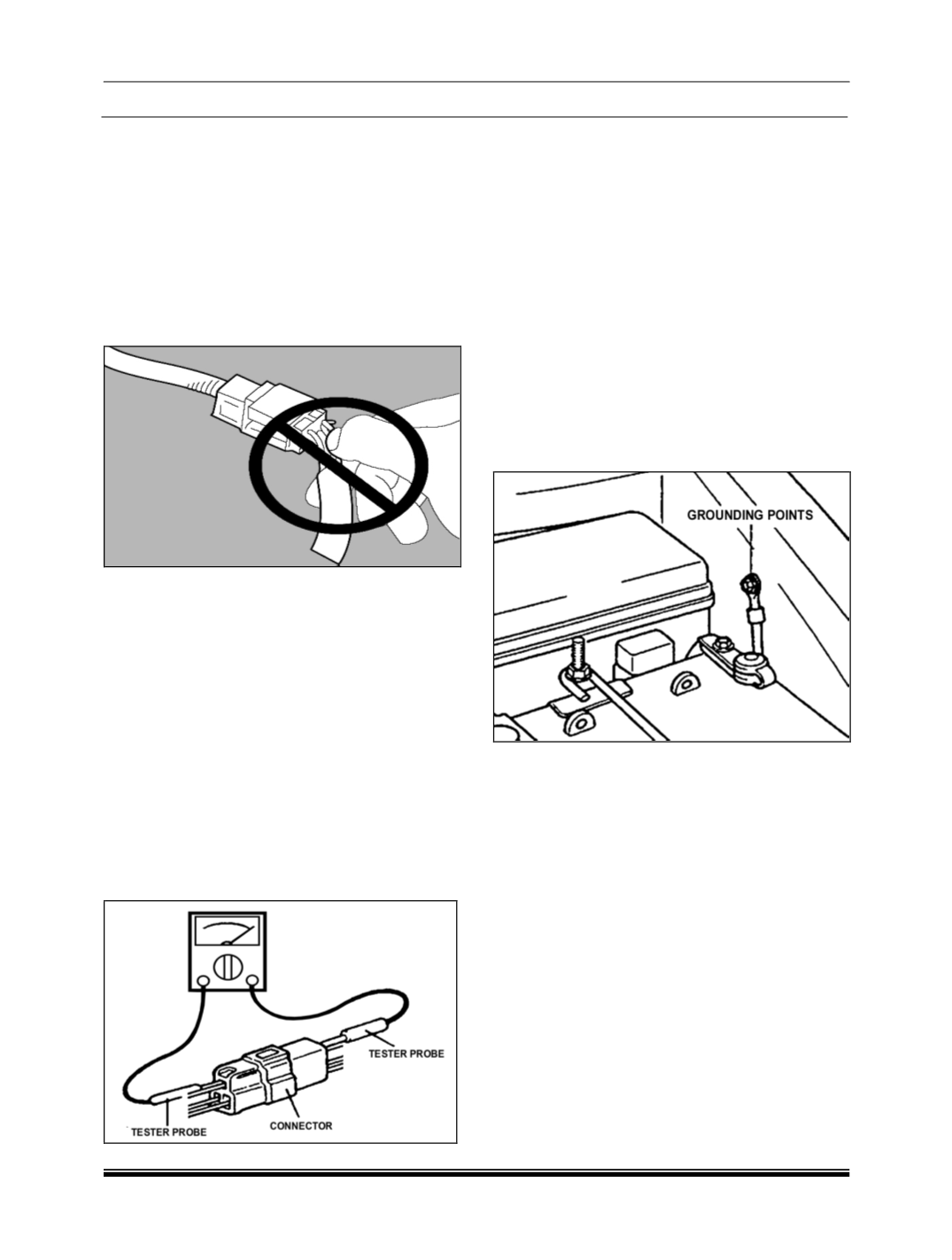
11.When using a circuit tester to perform continuity
or voltage checks or connector terminals, insert
the test probe from the harness side.
If the connector is a sealed connector, insert the
test probe in through the hole in the rubber cap for
the electrical wires, being careful not to damage the
insulation of the wires; continue to insert the test
probe until it contacts the terminal.
12.
In order to avoid overloading the wiring,
take the electrical current load of the optional
equipment into consideration, and determine the
appropriate wire size.
Checking cables and wires
a. Check the terminal for tightness
b. Check terminals and wires for corrosion by
battery electrolyte etc.
c. Check terminals and wires for open circuit or
impending open circuit.
d. Check wire insulation and coating for damage,
cracks and degrading.
e. Check conductive parts of terminals for contact
with other metallic parts (vehicle body and other
parts).
f. Check grounding parts to verify that there is
complete continuity between mounting bolt (s)
and vehicle body.
g. Check for correct wiring.
h. Check that wirings are clamped so as to prevent
contact with sharp corners of the vehicle body,
etc. or hot parts (exhaust manifold, pipe, etc.).
i. Check that the wirings are clamped firmly to
secure enough clearance from the pulley, belt
and other rotating or moving parts.
j. Check that the wirings between the fixed parts
such as the vehicle body and the vibrating parts
such as the engine are made with adequate
allowance for vibrations.