


 355 / 801

BRAKES
33
11. BRAKE PEDAL ASSEMBLY
REMOVAL
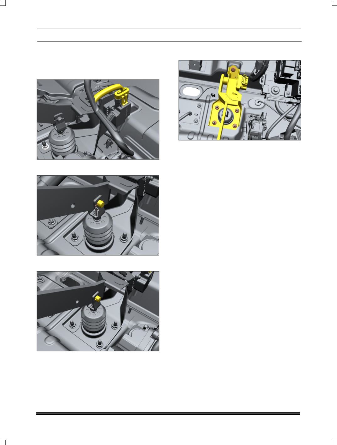
1. Disconnect
Electrical
connection
on
regenerative brake pedal sensor.
2. Remove split pin to disconnect pedal from
brake booster.
3. Remove clevis pin to separate booster
assembly from pedal.
4. Loosen and remove the brake mounting M8
nuts from panel firewall RHD.
INSTALLATION
1. Hold the brake control bracket on firewall.
2. Tighten the brake upper mounting M8 nut.
3. Tighten the brake mounting M8 nuts on panel
firewall RHD.
4. Match clevis hole to the pedal lever hole and
insert clevis pin into the hole.
5. Insert split pin in to the hole of clevis pin and
split the end of split pin.
NOTE:
1. Not to add carpet over the basic carpet in
the pedal region.
2. Basic carpet should be held firmly in the
pedal region.