


 468 / 745

HVAC
16
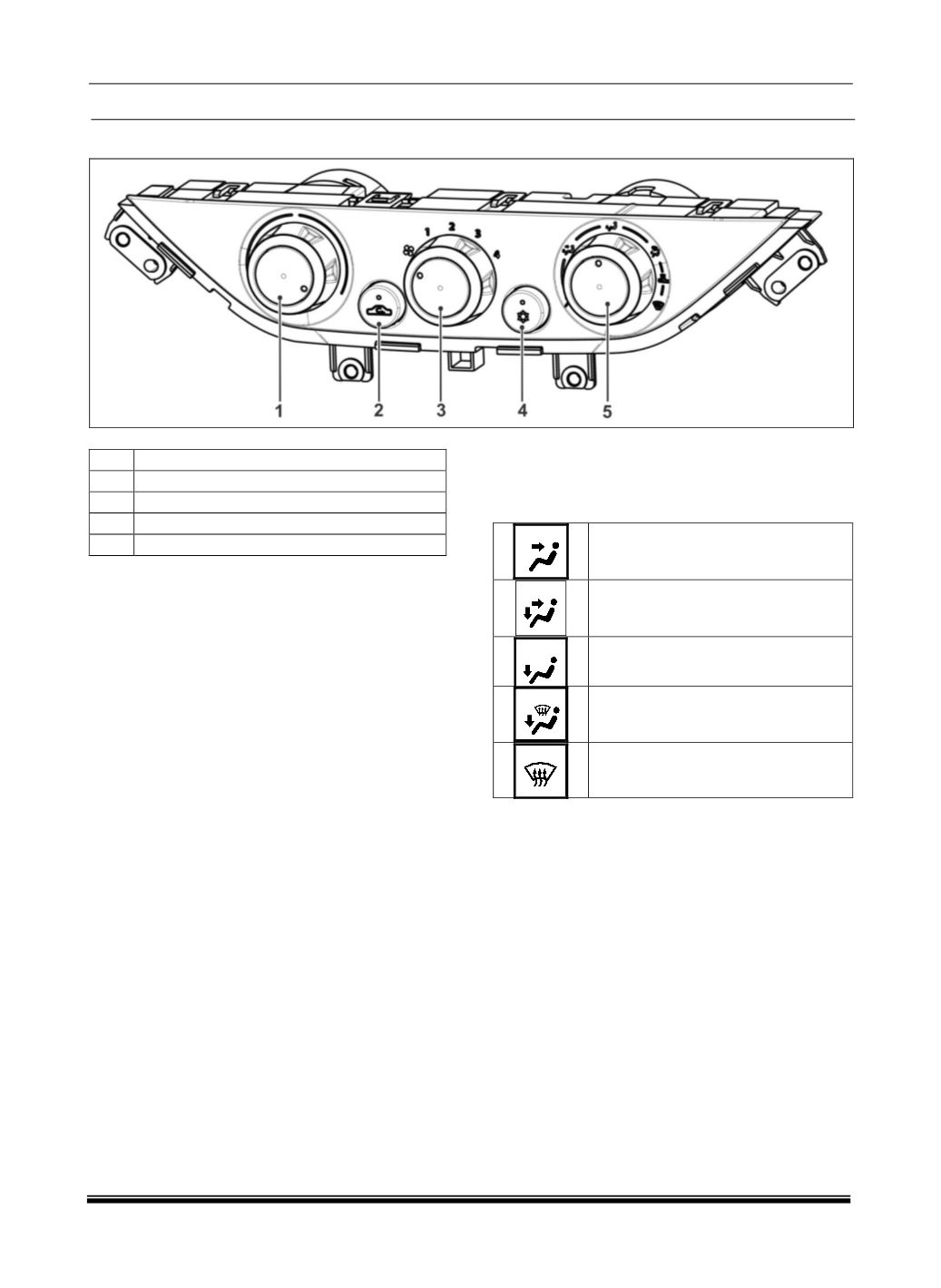
6. CONTROL PANEL
01
A\C TEMPRATURE SELECTION
02
FRESH AIR RECIRCULATION
03
BLOWER SPEED SELECTION
04
A\C BUTTON
05
A\C MODE SELECTION
The HVAC control panel consists of 2 Push buttons
and 3 rotary knobs that can be used to set the re-
quired temperature inside the cabin. In addition to
this the control panel also acts as a control unit for
the HVAC system in which all the software calibra-
tions are embedded.
1. PUSH BUTTONS
a. RECIRCULATION / FRESH AIR
This is a push button that can be used to position the
Air inlet door, either to allow fresh air to come inside
the cabin or to recirculate the air within the cabin.
b. NORMAL AC BUTTON
This is used to choose Normal AC or to switch OFF
the AC approximately 15mins.
2. ROTARY KNOBS
a. TEMPERATURE SELECTION
The temperature selector knob can be used to select
the required temperature varying from full cold
(on
the extreme anti-clockwise)
and full hot
(on the ex-
treme clockwise)
.
b. FAN SPEED SELECTION
The Fan speed selector allows the user to select four
blower speeds – 1, 2, 3 and 4. An OFF position” 0” is
also provided to shut the system off.
c. A\C MODE SELECTION
The mode knob is used to select the air delivery
mode. There are 5 different modes as given below.
Face Mode
Face – Leg Mode
Leg Mode
Leg – Defrost Mode*
Defrost Mode*
* See note below.
NOTE
When the Leg- defrost or Defrost mode is selected,
the HVAC control unit will select the recommended
settings for best performance of the selected func-
tion. These settings can be overridden by manual
intervention.
(For details refer HVAC layout and
working)