


 347 / 745

CLUTCH
9
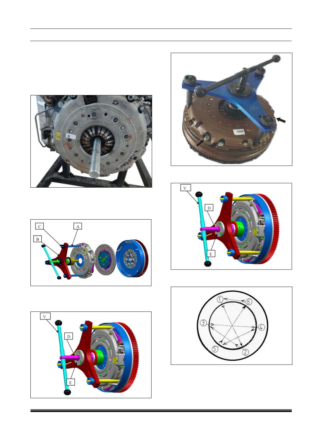
C. ASSEMBLY PROCEDURE:
Align the clutch set with DMF ensuring the
proper fitment direction of clutch disk. Centre
the pressure plate Assembly on the DMF
through three dowel pins & Align the clutch
set with the help of mandrel (5412 5890 2501)
& mount the 3 alternate bolts.
Assemble the three rods “A”, put the clutch
locking tool “B” & tighten the nuts “C” in the
upper end of Clutch alignment locking tool on
the on the clutch assembly.
Rotate bar “V” in clockwise direction till pin “D”
touches the collar “E”. This ensures complete
disengagement of clutch.
Assemble the 3 bolts.
Rotate the bar “
V
” in anti-clockwise direction
to engage the clutch and remove the tool.
Assemble the remaining 3 bolts & tighten all 6
bolts to 25Nm torque in cross direction.
Remove the Strap.
Remove
the flywheel locking tool.
Remove transaxle (Refer transaxle removal
procedure).