


 623 / 1003

STEERING
19
CAMBER ADJUSTMENT
1. Loosen the two strut mounting bolts.
2. Rotate the eccentric pin on top of the strut till
required camber value is achieved.
If not check eccentric pin for excessive wear. If so,
replace with new one.
3. First tighten the eccentric pin flanged nut to
specified torque & then tighten the bottom bolt
to specified torque.
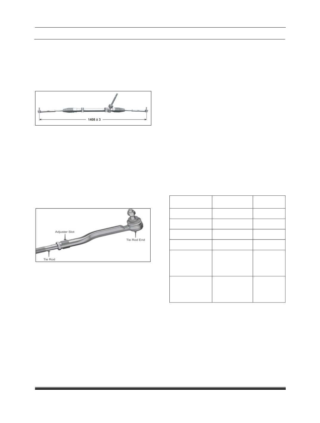
TOE OUT ADJUSTMENT
1. Loosen the tie rod end check nuts.
2. Steering rack and gear pinion comes with 1408
± 3 mm length between centers of the ball joint
with tie rods parallel to the rack. (As shown in
the following figure) Ensure that number of
threads of outer ball joints exposed out of the
tie rods same on LH and RH side.
3. Rotate the steering wheel from lock to lock.
Measure the number of turns
4. Bring the steering gear to center by rotating
through half the number of measured turns.
5. Remove the steering wheel & Refit it so that
spokes & mascot (T-emblem) are correctly
positioned.
6. Ensure that both front tyres are in straight
ahead position. Tighten the steering wheel nut
to specified torque.
7. Adjust toe-out as given below.
a. Toe-out is adjusted varying the lengths of tie
rods after loosening their lock nuts (as shown
in above figure). After adjusting the length of tie
rods recheck toe-in and tighten back the lock
nuts. Increasing length of tie rod will reduce the
toe-out and vice-versa.
b. While adjusting toe-out, adjust the length of both
tie rods by rotating them in the same direction
such that their length remains equal at all times.
8. Check the position of the T-emblem and the
spokes if the steering wheel is not centered,
adjust the tie rod lengths by reducing one and
increasing the other so that in the SAP (Straight
Ahead Parked) condition the toe is correct and
yet steering wheel is centered.
NOTE:
If toe is excessively out of limit, first adjust toe, then
the camber and then adjust toe again.
Not following the sequence i.e. first camber and
then toe out will lead to incorrect wheel alignment
even though individual adjustments are done
correctly.
After setting/adjusting steering geometry (i.e. Toe),
connect the diagnostic tool and follow the
instruction for ECU learning. This is applicable for
all variants fitted with EPAS.
WHEEL ALIGNMENT VALUES (In unladen
condition)
FRONT
REAR
Caster
3.7º ± 45’
-
Camber
-26' ± 26'
-52’ ± 30’
Toe In
10’ ± 5’
-3’ to + 27’
Toe Out
-
-
Camber angle
deviation
(Between LH &
RH)
20’
20’
Toe
angle
deviation
(Between LH &
RH)
13’
NOTE:
It is recommended to set toe & camber values
at mid of the specification range.
It is recommended to have minimum difference
between LH & RH set camber values. The
difference between LH & RH set values should
be within 20º maximum.
While removal and re-fitment of steering rack and
pinion assembly or replacing the tie rods on the
vehicle, the above procedure should be followed
before going in for actual wheel alignment.