


 845 / 924

FATC
17
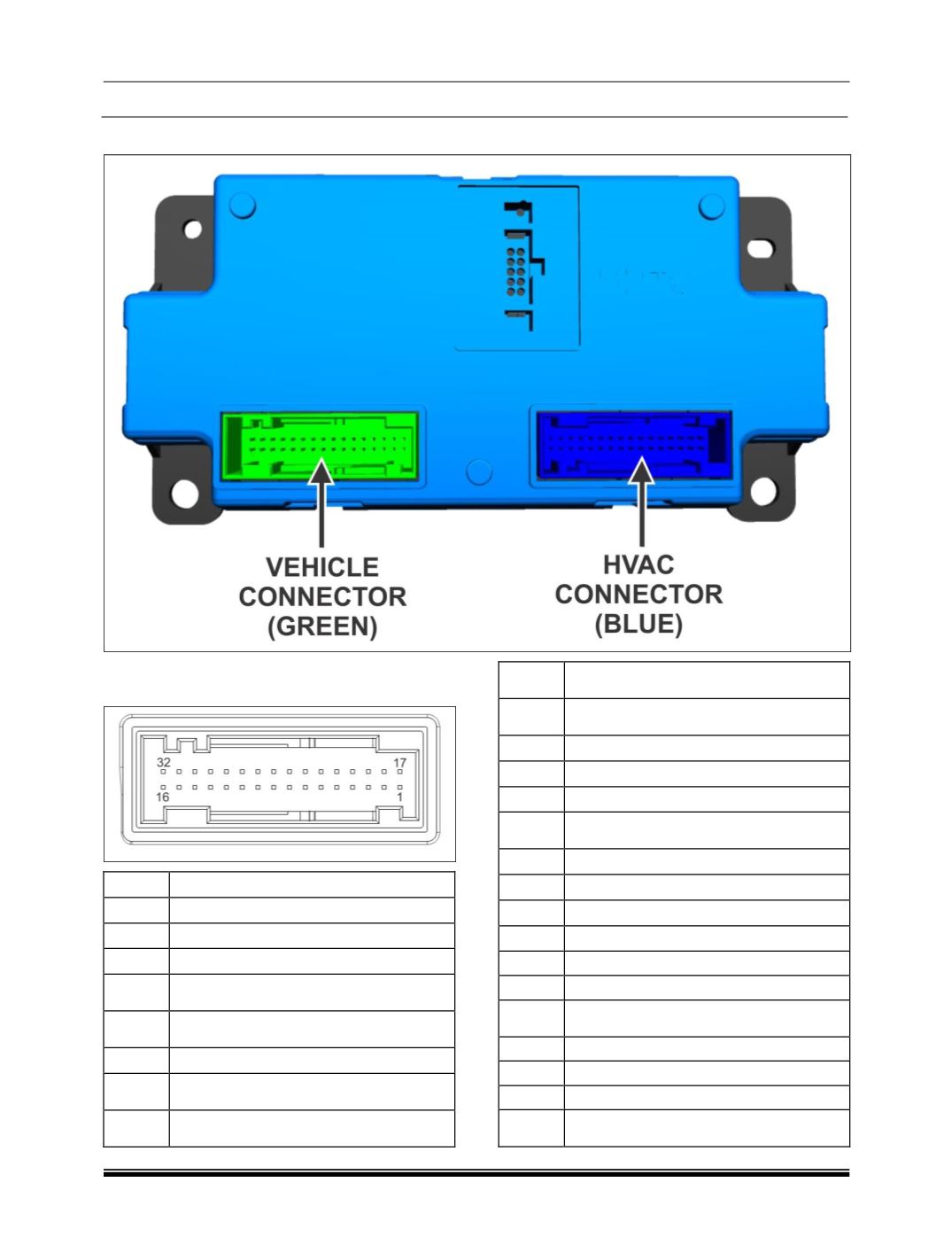
8. CONTROL PANEL MODULE CONNECTOR DETAILS
1. VEHICLE SIDE CONNECTOR (GREEN CON-
NECTOR) PINOUT DETAILS
PIN
DESCRIPTION
1
Battery Ground
2
Battery Ground
3
Battery Ground for CCH
4
Input signal from ambient temperature
sensor
5
Input signal from refrigerant tempera-
ture sensor
6
Input PWM signal
7
LIN channel for communication with
FATC Control head
8
Spare LIN channel for communication
with in-cabin components
9
Spare LIN channel for communication
with under-bonnet components
10
Input from Co-Driver side solar load
sensor
11
Air Conditioning Compressor Request
12
Input analog signal
13
Hardwired wake up signal from BCM
14
Reference voltage for non-HVAC sen-
sors
15
Permanent battery power supply
16
Permanent battery power supply
17
Signal ground for non-HVAC sensors
18
CAN Low
19
NC as per TML CAN IVN requirement
20
CAN High (Signal)
21
Input from Driver side solar load sen-
sor
22
CAN Low
23
NC as per TML CAN IVN requirment
24
CAN High
25
Humidity sensor(relative humidity in-
put)