


 736 / 924

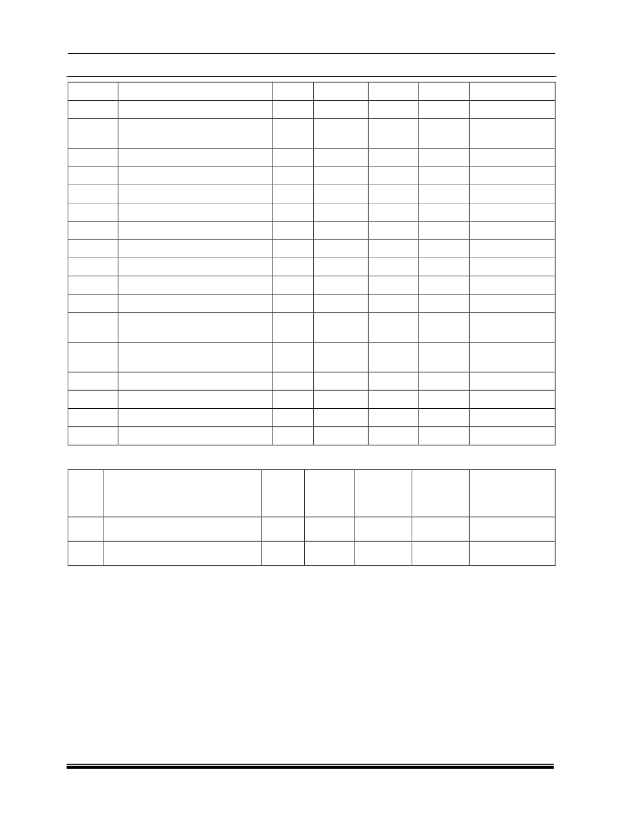
ELECTRICAL
118
20
Cockpit dimming Signal
Y
Analog
-
Input
-
21
Crash Signal_PWM
Y
PWM
Low
Input
-
22
Wiper Rear Fixed Internal
Signal
Y
Digital
Low
Input
-
23
ML Fail safe Switch Signal
Y
Digital
Config
Input
-
24
Spare4
Y
Analog
-
Input
-
25
LIN 2
Y
LIN
-
Bus
-
26
Battery GND3
Y
GND
-
Ground
-
27 - 37 NA
-
-
-
-
-
38
Roof Lamp LED Out
Y
PWM
High
Output
LED
39
DRL Position Lamp Control RH
Y
PWM
High
Output
Bulb/ LED
40
Head Lamp High Beam Relay
Y
Digital
High
Output
Ext. Relay
41 - 46 NA
-
-
-
-
-
47
Mirror Fold-
Y
Digital
High/Lo
w
Output
Motor
48
Mirror Unfold
Y
Digital
High/Lo
w
Output
Motor
49
NA
-
-
-
-
-
50
Cockpit Illumination
Y
PWM
High
Output
Bulb/LED
51
Spot LED Out
Y
PWM
High
Output
LED
52
DRL Position Lamp Control LH
Y
PWM
High
Output
Bulb/LED
•
CONNECTOR E: MATING SIDE HARNESS 2 PINS CONNECTOR CON 5
PIN
NO
SIGNAL NAME
USED
SIGNAL
TYPE
ACTIVE
LEVEL
SIGNAL
DESTIN-
ATION
LOAD
TYPE/
INPUT TYPE
1
Power Supply 3
Y
BATT
-
+VCC
-
2
-
-
-
-
-
-
NOTE:
Speed input be derived from instrument cluster speed output .Any changes regarding speed in the
instrument cluster may affect speed related functionality of BCM.