


 70 / 924

1.2L REVOTRON ENGINE
59
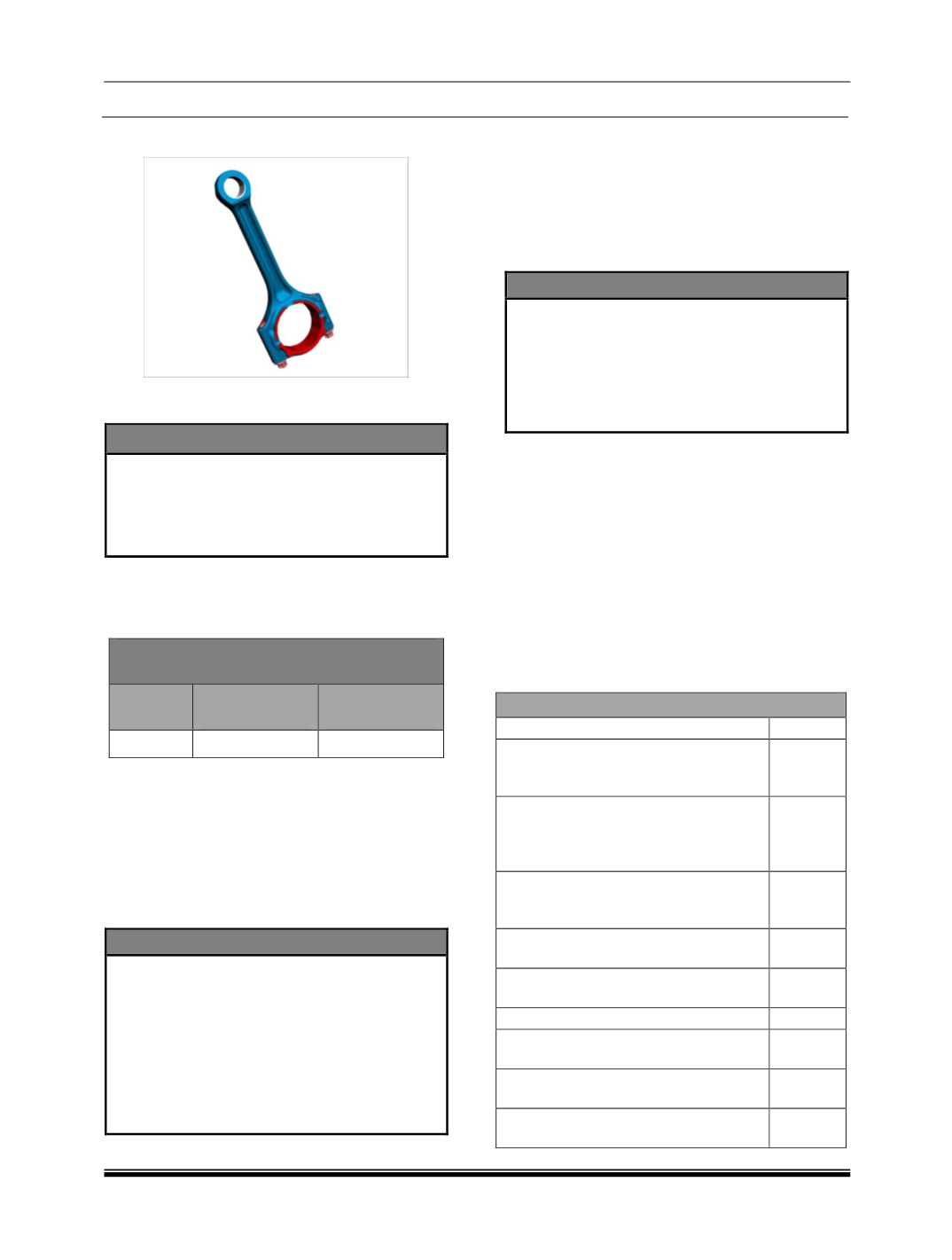
J. Connecting Rods :
1. Inspect the small end bush of connecting rod,
and measure piston-pin bore.
NOTE
Ensure that the connecting rod big end and
small end axes are parallel to each other.
Ensure that the Centre distance between
big end and small end is maintained within
the specified limits.
2. Install connecting rod bearing caps without
bearing shells.
3. Tighten connecting rod bearing caps
mounting bolts to the specified torque.
Connecting Rod – Small end Dimensions
(Revotron 1.2T)
Stage
Parent Bore
Diameter (mm)
Bush – outer
Diameter (mm)
Normal 21.000 - 21.021 21.055 – 21.095
4. Check for twist and bend of connecting rod by
using new piston pin at connecting rod small
end.
5. Using feeler gauge, measure twist and bend
of connecting rod with respect to vertical face
of connecting rod alignment gauge in both
vertical and horizontal plane at distance of
50mm, from the line joining centers of
connecting rod big and small end bushes.
NOTE
It is possible while installing the connecting
rod bearing cap will be off center, by which
dimension of connecting rod big end parent
bore will be different in different conditions.
If difference exists, connecting rod bearing
cap can be centralized by lightly tapping
with mallet, in the required direction after
loosening connecting rod bearing cap
mounting nuts.
6. Install new pair of connecting rod bearing
shell, depending on the size of crank pin
journal diameter. Make sure the securing lugs
are in the grooves of connecting rod and its
bearing cap.
7. Install connecting rod bearing cap with
bearing shell on connecting rod. Tighten
connecting rod bearing cap mounting nuts to
specified torque.
NOTE
Correct bearing bore dimensions can be
achieved if connecting rod big end parent
bore dimension is maintained.
Measure pre-tension of connecting rod
bearing shell with a feeler gauge after
loosening connecting rod bearing cap
mounting nuts.
8. Measure connecting rod big end parent bore
dimension. If connecting rod big end parent
bore is slightly more than maximum
permissible limits, then the connecting rod
can be reclaimed provided the wear is
confined to connecting rod bearing cap. If the
mating surface of the connecting rod bearing
cap is slightly faced, then the parent bore
should be given a finishing on a connecting
rod boring machine.
9. If one or more connecting rods are to be
replaced, the difference in weight of
connecting rod should be within the
permissible limit.
Maintenance Limit (REVOTRON 1.2L) in mm
Small end parent bore cylindricity
0.008
Connecting rod small end bush
inside diameter (finished after
installation)
18.007 /
18.020
Maximum permissible out of
parallelism
(bend)
between
connecting rod small end and big
end parent bores.
0.015
Center to center distance between
connecting rod small end and big
end parent bores
138.8
±
0.03
Maximum permissible twist of
connecting rod
0.030
Connecting rod big end parent bore
diameter
45.000 /
45.016
Big end parent bore and cylindricity
0.01
Bearing shell to be selected such
that clearance is maintained as
0.027 -
0.066
Crush height of connecting rod big
end bearing shells
0.025 -
0.055
Connecting rod big end axial play
0.05 -
0.35