


 408 / 948

Anti-lock Braking System(ABS)
16
3. REPAIRS :
Precautions:
Before undertaking any electric arc welding
work, disconnect the ABS ECU's connector.
During paintwork operations or major repair
work, which are likely to subjected to higher
temperature (above 85° C), The HCU must be
removed.
Before removing the ECU, the battery must
be disconnected. Terminals must be fully
tightened while installing battery.
Electrical wiring should not to be repaired it
should be replaced.
WARNING:
When the hydraulic connections to the hydraulic
modulator can be crossed over; the ECU self-
diagnosis will not detect it as a fault; nor will it
cause the system to be shut down or cause a fault
code to be logged in the ECU. When the hydraulic
modulator is exchanged or repaired, the brake
pipes to the solenoids must be tested for correct
assignment using a diagnostics tester. When the
inlet and outlet valve are activated, e.g. on the
front left wheel, this must generate the necessary
changes at the wheel. If this does not happen, the
pipes have been crossed over. This will cause the
system to function incorrectly.
Brake System Bleeding:
NOTE:
For brake bleeding procedure conventional/ using
diagnostic tool refer Brakes group.
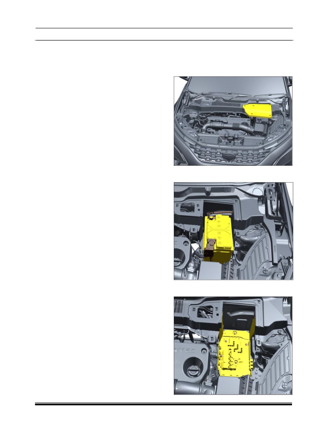
A. ABS ECU/HCU REMOVAL
Removal:
1. Turn OFF the ignition switch.
2. Remove the middle leaf screen cover.
3. Disconnect the battery cables and remove the
battery.
4. Remove the mounting bolts and take out the
battery tray.