


 413 / 948

Anti-lock Braking System(ABS)
21
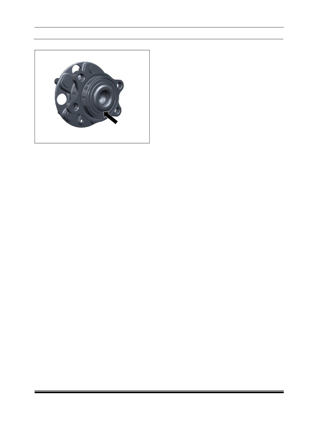
E. REAR MAGNETIC ENCODER :
1. Rear axle wheel end, axle shaft and Bearing
needs to be removed for Encoder Inspection.
(for procedure refer Rear Axle section)
2. If any damage is visible on encoder rubber
strip on bearing replace the bearing with
encoder strip. (Refer Rear Axel section for for
bearing replacement procedure)
4. TROUBLE SHOOTING AND DIAGNOSIS :
While the key is in IGN position, the ABS ECU
monitors the system for faults. Diagnostic
information and system function monitoring can
be accessed by connecting diagnostic tool to the
vehicle diagnostic connector.
After detecting a fault, the ABS ECU will select a
suitable default strategy which will retain, if
possible, some operational ABS capability. If ABS
is not active, conventional braking will remain
available.
A. ROAD TEST :
WARNING :
It is essential that brake pedal travel is not
obstructed by items such as extra floor mats.
(a) While driving the vehicle with ABS :
Observe the warning lights, check parking
brake/fluid warning light extinguishes after initial
bulb check and when the parking brake is
released, indicating that power assistance is
available.
(b) Normal ABS brake operation :
In road conditions where surface friction is
sufficient to slow or stop the vehicle without wheel
lock, ABS does not operate.
In an emergency braking situation, if one or more
wheels begin to slow rapidly in relation to vehicle
speed, ABS will detect wheel locking tendency
and will regulate brake pressure to maintain wheel
rotation.
(c) Brake application with partial failure :
WARNING :
If a fault develops in the brake system it is
essential that it is investigated immediately.
i. TMC failure :
If during braking, a drastically reduced resistance
is detected at the pedal and braking effectiveness
is very much reduced, failure of the non-powered
(master cylinder) portion of system is indicated. If
this occurs, do not pump the brake pedal. Push
the pedal through free movement to obtain
braking effort from the power circuit.
ii. Brake Booster failure :
When power assistance is not available, braking
effort is only available from the master cylinder In
this case the pedal travel will be or feel shorter as
there is no assistance and greater effort will be
required to stop the vehicle.