


 706 / 948

ELECTRICAL
81
PINOUT DETAILS
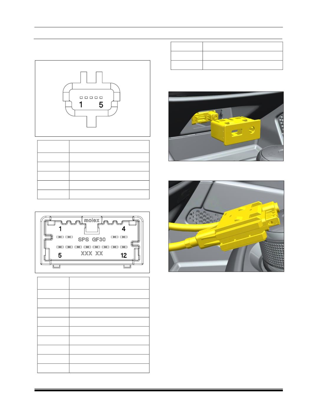
1. USB Connector
PIN
DESCRIPTION
1
USB_5V
2
USB_D -
3
USB_D +
4
NC
5
GND
2. AUX Connector
PIN
DESCRIPTION
1
ILLUM -
2
ILLUM +
3
NC
4
NC
5
BAT
6
NC
7
AUX SHIELD
8
AUX_R
9
AUX_L
10
AUX_COM
11
AUX_DECT
12
GND
REMOVAL
1. Gently pry out the module from the cutout.
2. Disconnect the electrical connections & take out
the switch assy.
REFITMENT
For refitment follow the procedure in reverse.