


 453 / 948

HVAC
18
8. COMPRESSOR
SPECIFICATION
MODEL
SD7V16
MAXIMUM DIS-
PLACEMENT
161.3 cm
3
/ rev
.
MINIMUM DIS-
PLACEMENT
9.7 cm
3
/ rev
.
LUBRICANT
SP10 or Equivalent
OIL QUANTITY
135 cm
3
The Compressor used in the vehicle is variable dis-
placement type.
This compressor has two identical scrolls arranged
at 180º around a offset center; one of them is fixed
(fixed scroll) and the other (orbit scroll) is turned at a
constant attitude, so that the space made between
the scrolls symmetrically around the rotating shaft
moves from outside toward the center while reducing
its volume; this is the principle of compression.
The moving scroll rolls and slides in small circular
movement with a small friction loss, ensuring smooth
operation even during start-up.
COMPRESSOR RELAY
Compressor relay is located in the MDU (
Main distri-
bution Unit)
located in the engine compartment
which is used to operate the compressor magnetic
clutch. The magnetic clutch continues to operate as
long as air conditioner is under operation. Once the
air conditioner is put in OFF condition, the compres-
sor relay gets cut off and the magnetic clutch gets
disengaged from the compressor. The cut - in and
cut - off of relay is governed by the ENGINE ECU.
The HVAC control unit controls the compressor
ON/OFF indirectly by sending ON/OFF request to
the EMS ECU.
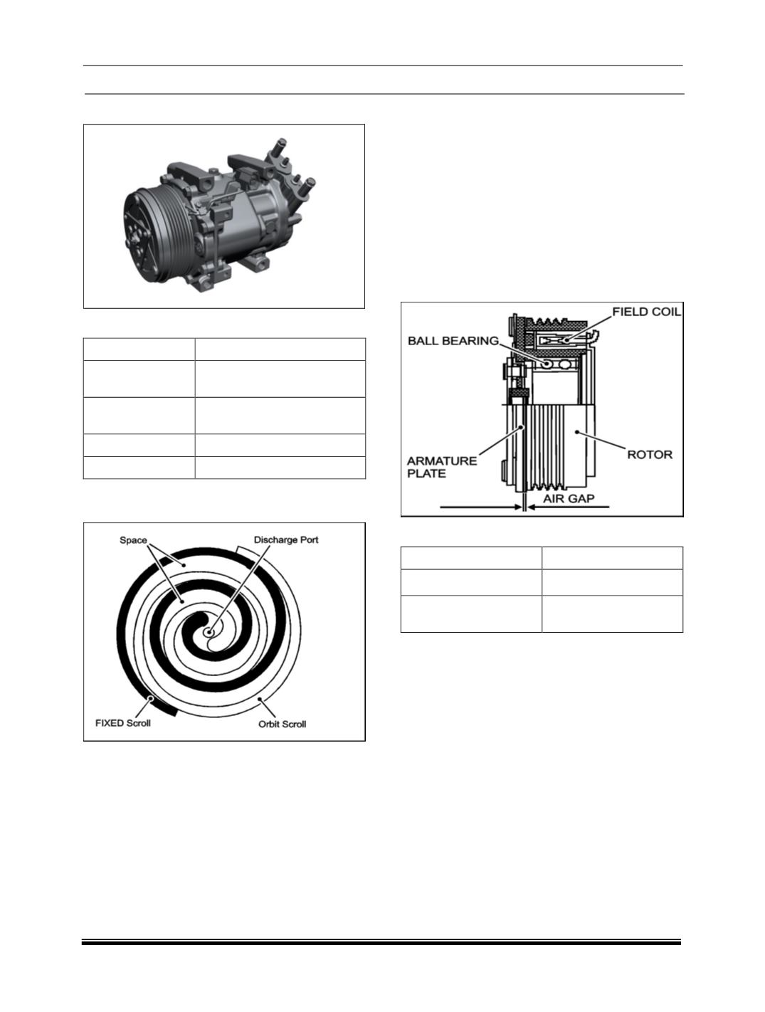
MAGNETIC CLUTCH
SPECIFICATION
NOMINAL VOLTAGE
DC12V
AIR GAP
0.4 TO 0.8MM
DIRECTION OF
ROTATION
CLOCKWISE
Meet jaso e111-06, 6pka - magnetic clutch is used to
connect and disconnect the compressor from the
engine.
Main components are stator, rotor, and pressure
plate.
PRINCIPLE
When the current is fed to the coil magnetic force is
generated in iron, which attracts any other iron.
CONSTRUCTION
A magnetic clutch consists of a stator, rotor with pul-
ley, and pressure plate to engage the drive pulley
and compressor magnetically. The stator is fixed on
the compressor housing, and the pressure plate is
attached to the compressor shaft. Two ball bearings
are used between the inner surface of the rotor and
the front housing of the compressor.
OPERATION