


 332 / 948

BRAKES
2
3. SYSTEM DETAILS
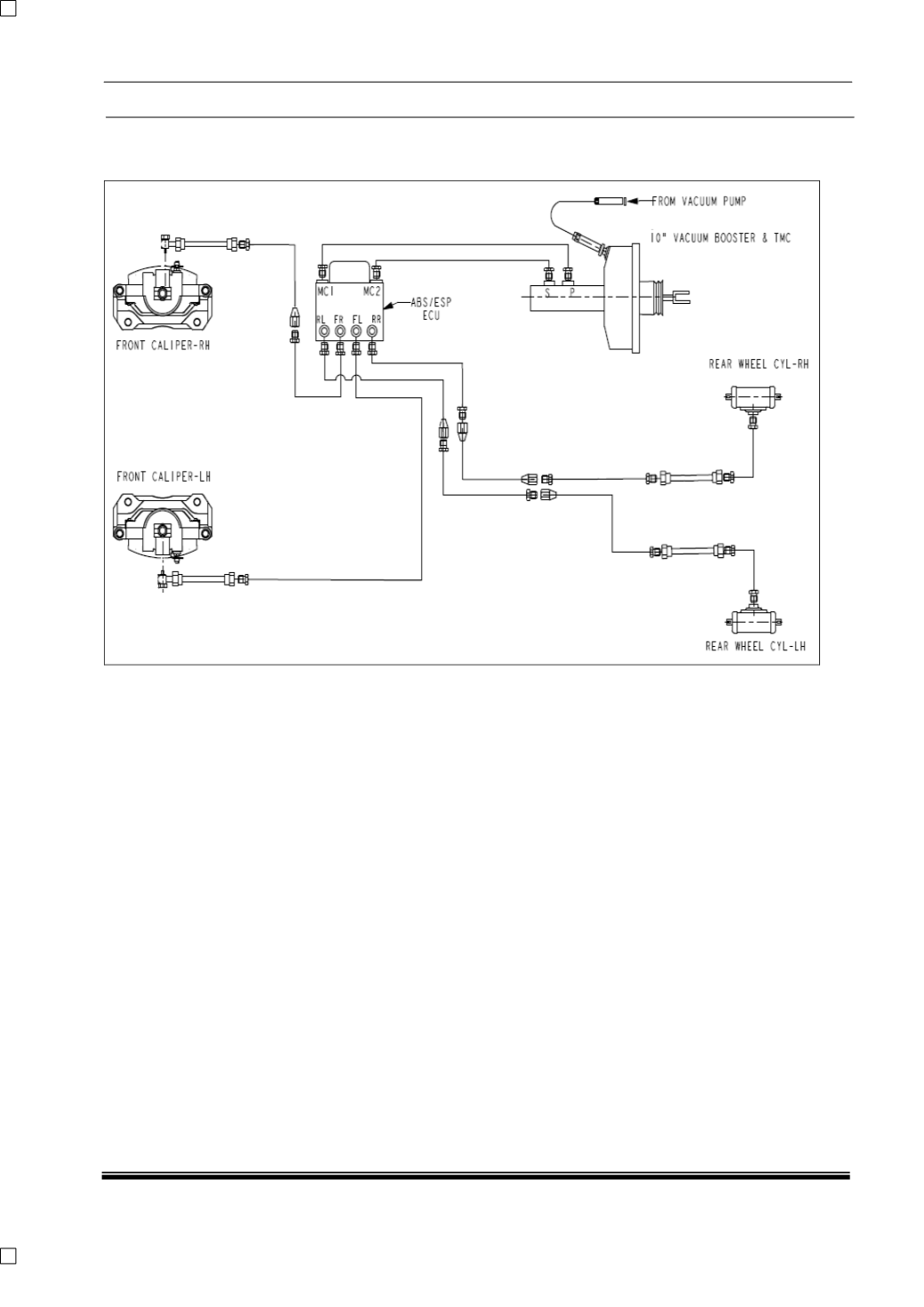
A. SYSTEM SCHEMATIC FOR ABS & ESP VERSION
General:
Vehicle braking is provided by Disc Brakes on
the front wheels and Drum Brakes on the rear
wheels.
Under normal brake operation, brake pedal
movement is assisted by the Booster assembly
and transmitted to the Tandem Master Cylinder
(TMC) assembly. The TMC assembly converts
brake pedal movement to hydraulic pressure.
Vacuum for the brake servo assembly is
obtained from the engine inlet manifold (for
petrol engines) or a vacuum pump (for diesel
models), through a vacuum line and non-return
valve.
Anti-lock braking system consists of a Hydraulic
modulator with integrated Electronic control unit,
four-wheel speed sensors (one located at each
wheel) and 2 warning lamps in the instrument
cluster (1(yellow for ABS and 1(Red) for EBD).
The brake pipes are connected to the brakes
through the ABS ECU / HCU. They make two
independent circuits diagonally split. The primary
circuit connects the Front Right and the Rear
Left brake while the secondary connects Front
Left and Rear Right brake through ABS unit.
Internal to the Hydraulic modulator each brake
has a pair of solenoid valves, one inlet and one
outlet; these are activated by the ECU to control
the brake force on individual wheels whenever
required.