


 344 / 948

BRAKES
14
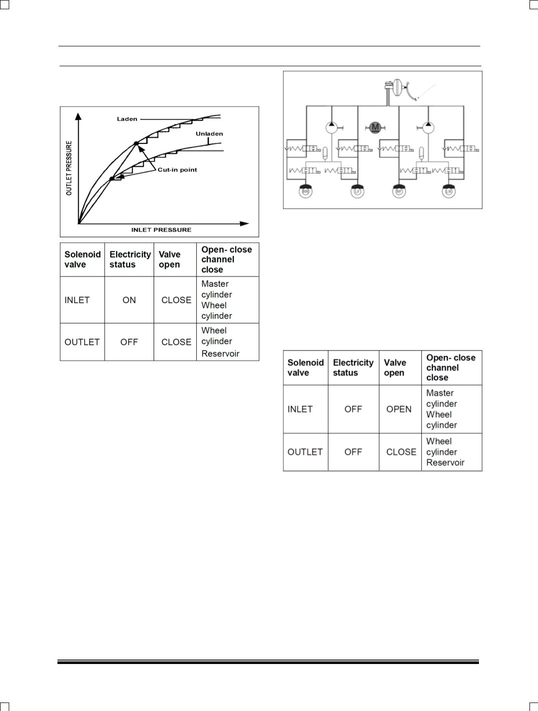
EBD control only acts upon the rear axle and can
only limit pressure being applied to a rear wheel; it
cannot perform pressure reductions.
Fig: Pressure increase on rear axle following
ideal brake force distribution curve.
C. BRAKING WITH ABS INTO OPERATION:
In the case of braking where the ABS ECU detects
a significant difference in the wheel speed
information from the individual wheels. The
electronic control unit instructs the hydraulic
modulator to modulate the brake pressure being
applied at the affected wheel(s). There are three
stages to this control.
Pressure increase Phase:
As the ECU detects that the speed of the
controlled wheel has increased to the vehicle
reference speed and hence the % slip reduced. It
will sequentially deactivate the outlet and inlet
valves switching them to their normal positions.
With the outlet valve closed further pressure
reduction is prevented and the inlet valve can be
opened to allow brake fluid from the TMC to enter
the wheel brake increasing the brake pressure
once again. If the driver releases the brake at any
time during ABS control the inlet valves will be
deactivated and fluid can return to the TMC via the
inlet valve and the one-way valve.
D. Pressure Maintaining (Hold) Phase:
When the braking forces being applied are higher
than can be transmitted to the road surface for a
specific wheel the ECU will detects that wheel as
tending towards lock (Slip relative to other wheels
and a calculated vehicle reference speed). It will
activate the relevant Inlet valve within the hydraulic
modulator, switching it from its normally open
position to closed, hence preventing further
pressure being transmitted from the TMC to the
affected wheel brake. As the outlet valve is also
closed in this phase the pressure at the wheel is
maintained.