


 229 / 948

CLUTCH RELEASE SYSTEM
11
9. BRAKE
SWITCH
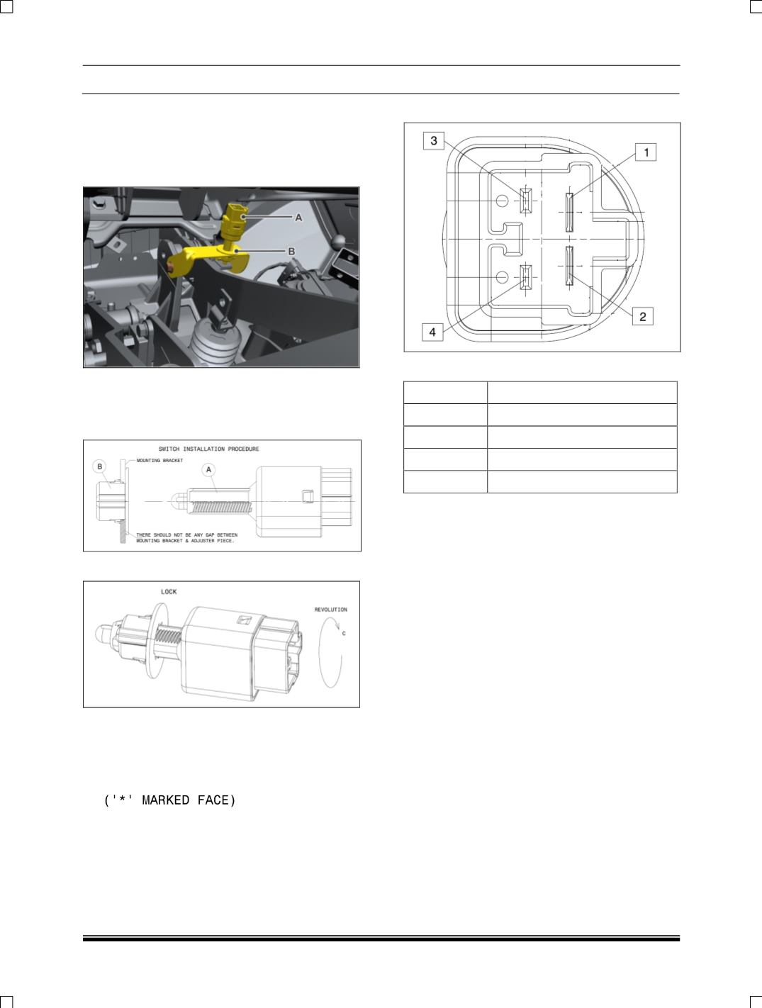
INSTALLTION
PROCEDURE
1. Adjuster to be snapped on mounting Bracket,
there should not be play in the adjuster after
fitment with mounting bracket.
2. Insert the switch (A) in Adjuster (B) till the
switch plunger get completely pressed against
brake pedal (At this point switch body will rest
on brake pedal)
3. Rotate the switch in direction ‘C’ till its Lock.
4. After Locking the switch will set back by
1±0.15 mm.
5. Allowable angular Tolerance for the operation
of pedal is ±1º and will be checked from the
top
face
of
switch
Body
.
BRAKE SWITCH CONNECTOR DETAILS
PINOUT DETAILS
PIN NO.
FUNCTION
1
TERMINAL
2
FITMENT
3
OPERATION
4
ADJUSTER PIECE