


 741 / 1232

BRAKES
14
C. BRAKING WITH ABS INTO OPERATION:
In the case of braking where the ABS ECU
detects a significant difference in the wheel speed
information from the individual wheels. The
electronic control unit instructs the hydraulic
modulator to modulate the brake pressure being
applied at the affected wheel(s). There are three
stages to this control.
1. Pressure increase Phase:
As the ECU detects that the speed of the
controlled wheel has increased to the vehicle
reference speed and hence the % slip reduced. It
will sequentially deactivate the outlet and inlet
valves switching them to their normal positions.
With the outlet valve closed further pressure
reduction is prevented and the inlet valve can be
opened to allow brake fluid from the TMC to enter
the wheel brake increasing the brake pressure
once again. If the driver releases the brake at any
time during ABS control the inlet valves will be
deactivated and fluid can return to the TMC via
the inlet valve and the one way valve.
Solenoid
valve
Electricity
status
Valve
open
Open- close
channel close
INLET
OFF
OPEN
Master
cylinder
Wheel cylinder
OUTLET OFF
CLOSE Wheel
cylinder
Reservoir
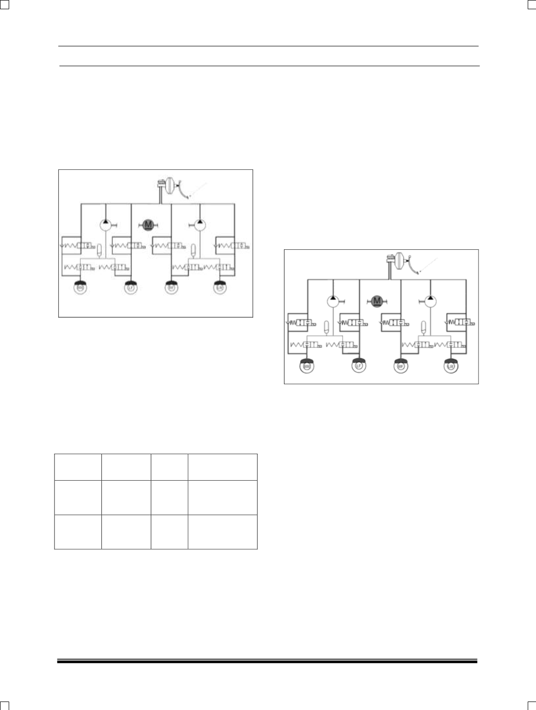
2. Pressure Maintaining (Hold) Phase:
When the braking forces being applied are higher
than can be transmitted to the road surface for a
specific wheel the ECU will detects that wheel as
tending towards lock (Slip relative to other wheels
and a calculated vehicle reference speed). It will
activate the relevant Inlet
valve within the
hydraulic modulator, switching it from its normally
open position to closed, hence preventing further
pressure being transmitted from the TMC to the
affected wheel brake. As the outlet valve is also
closed in this phase the pressure at the wheel is
maintained.
If the driver reduces the brake pedal effort during
ABS control brake fluid can return to the TMC
through the one way valve located within the
modulator in parallel to the Inlet valve.
3. Pressure Reduction Phase:
If the ECU detects that the % Slip relative to the
other wheels and vehicle reference speed is still
increasing during the pressure hold phase and the
wheel is tending further towards lock it will start
the pressure reduction phase as the existing
brake pressure in the wheel brake is too high. It
will activate the relevant outlet valve within the
hydraulic modulator, switching it from its normally
closed position to open. This will allow fluid to
pass from the wheel brake into the accumulator
chamber within the modulator. At the same time
the ECU will activate the return pump integrated
into the modulator to draw fluid from the
accumulator and wheel brake and return it to the
TMC. This fluid being returned to the TMC is what
is felt as the pulsations at the pedal, and the
amplitude of the pulsations is relative to the
amount of fluid that needs to be reduced.
Pressure reduction will continue until controlled
wheel returns to the vehicle reference speed.