


 447 / 1232

ENGINE 1.3L QUADRAJET (90PS)
110
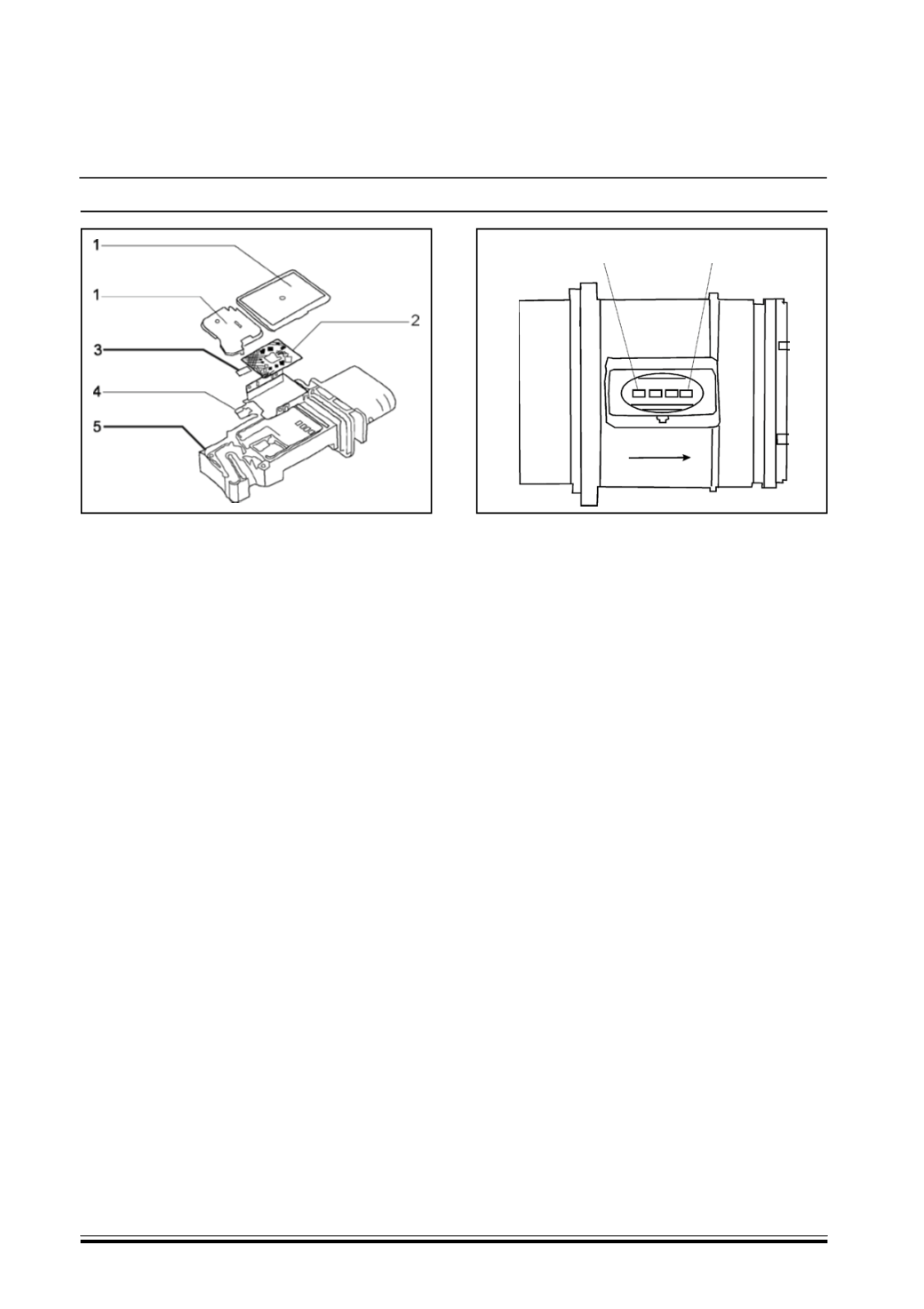
1. Electronic circuit cover and measuring duct cover
2. Electronic control circuit
3. Sensitive element with intake air temperature
sensor incorporated
4. Electronic circuit metal support plate and sensitive
element
5. Plastic support casing
NOTE :
The air flow meter cannot be dismantled
PIN OUT
1. 12 V power supply
2. Earth
3. Air temperature signal
4. Air mass signal
OPERATION
The operating principle is based on the heating of a
diaphragm (sensitive element containing two
resistances upstream and downstream of the
support) in a by-pass duct through which the engine
intake air flows.
The hot film membrane is maintained at constant
temperature (about 120 °C higher than the incoming
air temperature) by the specific heating resistance
controlled by the management electronics.
The mass of air passing through the by-pass duct,
giving off heat to the membrane, thermally
unbalances the two resistances to an extent directly
proportional to the mass of the incoming fluid, an
imbalance that is translated through the control circuit
into a resistance variation, electronically processed
and translated into a frequency value to be sent to
the engine management control unit.
The imbalance in the resistance value also makes it
possible to determine the direction of the column of
air.
As far as the air temperature information is
concerned, it is sent to the engine management
control unit via a dedicated pin in the form of a duty
cycle signal (rectangular wave). The value of the duty
is proportional to the value of the temperature.
NOTE :
The flow meter measures the air mass directly (not
the volume) to eliminate problems of compensation
correlated to the temperature, altitude, pressure
values etc.
1
4