


 317 / 1232

ENGINE 1.3 QUADRAJET (75PS)
92
Fig. 179
OPERATION
A current-carrying semiconductor layer immersed in
a normal magnetic field (force lines at right angles to
current direction) generates a potential dif ference
known as a Hall voltage at its terminals.
If current intensity remains constant, the generated
voltage depends on magnetic field intensity alone.
Periodic changes in magnetic field intensity are
sufficient to generate a modulated electrical signal
with frequency proportional to the speed of magnetic
field change.
To produce this change, a tooth on the inner part of
the pulley periodically moves close to the sensor.
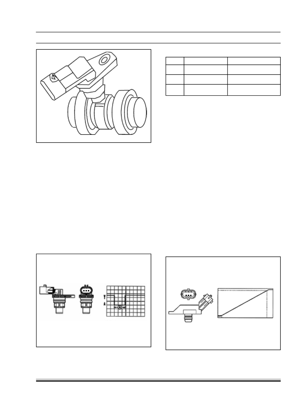
Fig. 180
PIN_OUT
Pin
Description
Signal type
1
Earth
Earth
2
Timing signal
Frequency output
3
Power supply 12 V input
In the specific case of the timing sensor it receives a
5 Volt power supply from the engine management
control unit.
All the times the rotor passes in front of the sensor a
variation in the actual sensor output volt age is
produced through the Hall efect; this variation takes
place for the entire duration that the rotor passes in
front of the sensor after which the signal returns to
the original value (5V).
D. PRESSURE RELIEF SENSOR - FOR THE 75
CV VERSION
SPECIFICATIONS
The supercharging pressure sensor is fitted on the
intake manifold and allows int ake pressures up to
1.5 bar to be measured (corresponding to 2.5 bar
absolute).
The sensitive element comprises a piezoresistive
element whose signal is amplified by an electronic
circuit built into the sensor . The sensor receives a
direct 5 V supply from the electronic control unit and
provides an output voltage directly proportional to the
supercharging pressure.
Fig. 181
10 ms
5 V
3 2 1
1 2 3
(v)
5
4.95
0.04
0 20
250 (kPs)