


 1110 / 1232

ELECTRICAL
75
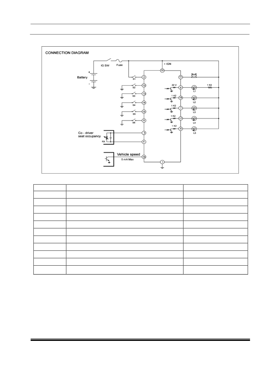
Connection diagram:
Connection details:
Designation
Function
Locatio
n
L1
Driver seat belt not fastened
Instrument cluster
L2
Co - driver seat belt not fastened
Fac
ia
L3
Rear left seat belt not fastened
Fac
ia
L4
Rear middle seat belt not fastened
Fac
ia
L5
Rear right seat belt not fastened
Fac
ia
S1
Reverse gear
Gearb
ox
S2
Driver seat belt fastened
Seat buckle
S3
Co - driver seat belt fastened
Seat buckle
S4
Rear left seat belt fastened
Seat buckle
S5
Rear middle seat belt fastened
Seat buckle
S6
Rear right seat belt fastened
Seat buckle
SEAT BELT OCCUPANCY SENSOR
This system has flexible printed circuit board integrated in the co-driver seat foam (bottom). It has multiple
sense point and electrical resistance offered by the system to the controller WHICH changes if seat is
occupied.
Seat occupied - 0 to 100 Ohms
Seat unoccupied - 1000 Ohms and above
Between 100 to 1000 Ohms its grey area and controller assumes earlier position.