


 562 / 1232

Automated Manual Transmission
34
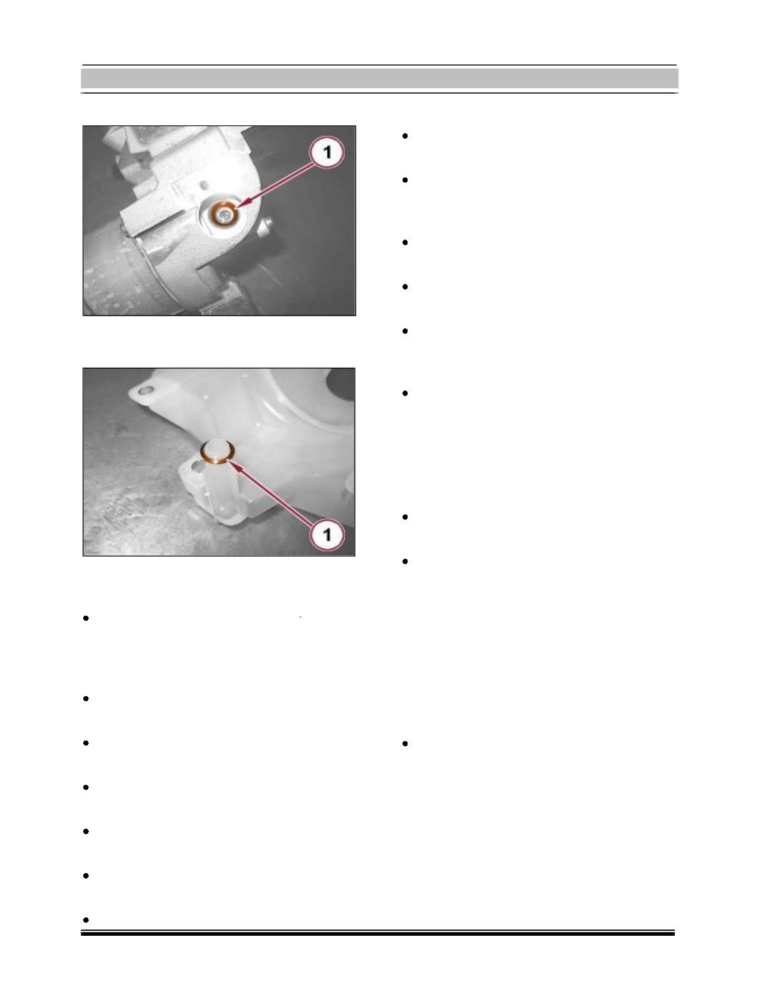
1. Remove the O-ring from the electric pump.
1. Remove the ring for the connector on the
reservoir.
Electro Hydraulic Circuit Reservoir And Sys-
tem Pump Fitment:
Place the hydraulic circuit fluid reservoir in
its housing complete with ring for the con-
nector and tighten the corresponding
screws.
Place the hydraulic circuit pressure sensor
in its housing and screw it in.
Place the wiring retaining clip in its housing
and tighten the corresponding screw.
Place the hydraulic circuit fluid reservoir
mounting in its housing.
Connect the electrical connection for the
gearbox input speed sensor.
Connect the electrical connection for the
electric pump.
Tighten the hydraulic circuit fluid reservoir
mounting upper fixing screw.
- Connect the electrical connection for the
hydraulic circuit pressure sensor.
Tighten the connector for the pipe from
electric pump to hydraulic unit, electric
pump side.
Place the protection /guard under the en-
gine.
Place pressure accumulator on hydraulic
actuator unit.
Place the heat protection bulkhead on
gearbox hydraulic circuit fluid reservoir
with electro hydraulic selection.
Refill the electro-hydraulic selection gear-
box hydraulic control system, with
reference to
Hydraulic system fluid for gearbox with
hydraulic selection checks level and top
up, if necessary
Place the battery, battery tray and connect
the battery.
Connect the diagnosis equipment and carry
out the following operations:
Hydraulic system for gearbox with hy-
draulic selection - bleed air
Clutch self-calibration enablement.
Grid self tuning - service.
New actuators (only if the hydraulic actu-
ation unit is being replaced).
Remove the Car from the lift.