


 540 / 1232

Automated Manual Transmission
12
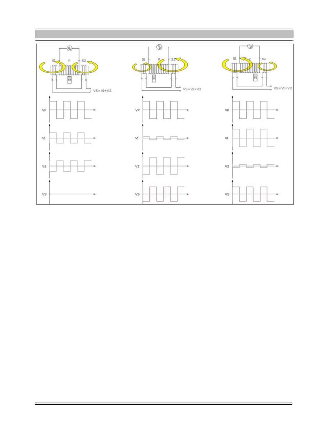
This image shows the variation of the output
voltage (VS) according to the position of the
magnet. As the sensor operates with an
alternating voltage, regardless of the
movement of the magnet to the right or
the left of the sensor, the effective value of
the output voltage will be the same.
To determine whether the movement of the
magnet is to the left or to the right, the
electronic sensor control circuit analyses the
phase difference between the VP voltage
applied to the primary coil and the total
voltage VS.
If the phase of the voltage VS is the same of
the phase of the voltage VP, the magnet
moves to the right and vice versa.
Technical data:
Primary resistance 35 Ω +/- 15%
Secondary resistance 21 Ω +/- 15%
NOTE:
The electronic circuit to read the signal gen-
erated by the PLCD is installed inside the
NCR.