


 319 / 1232

ENGINE 1.3 QUADRAJET (75PS)
94
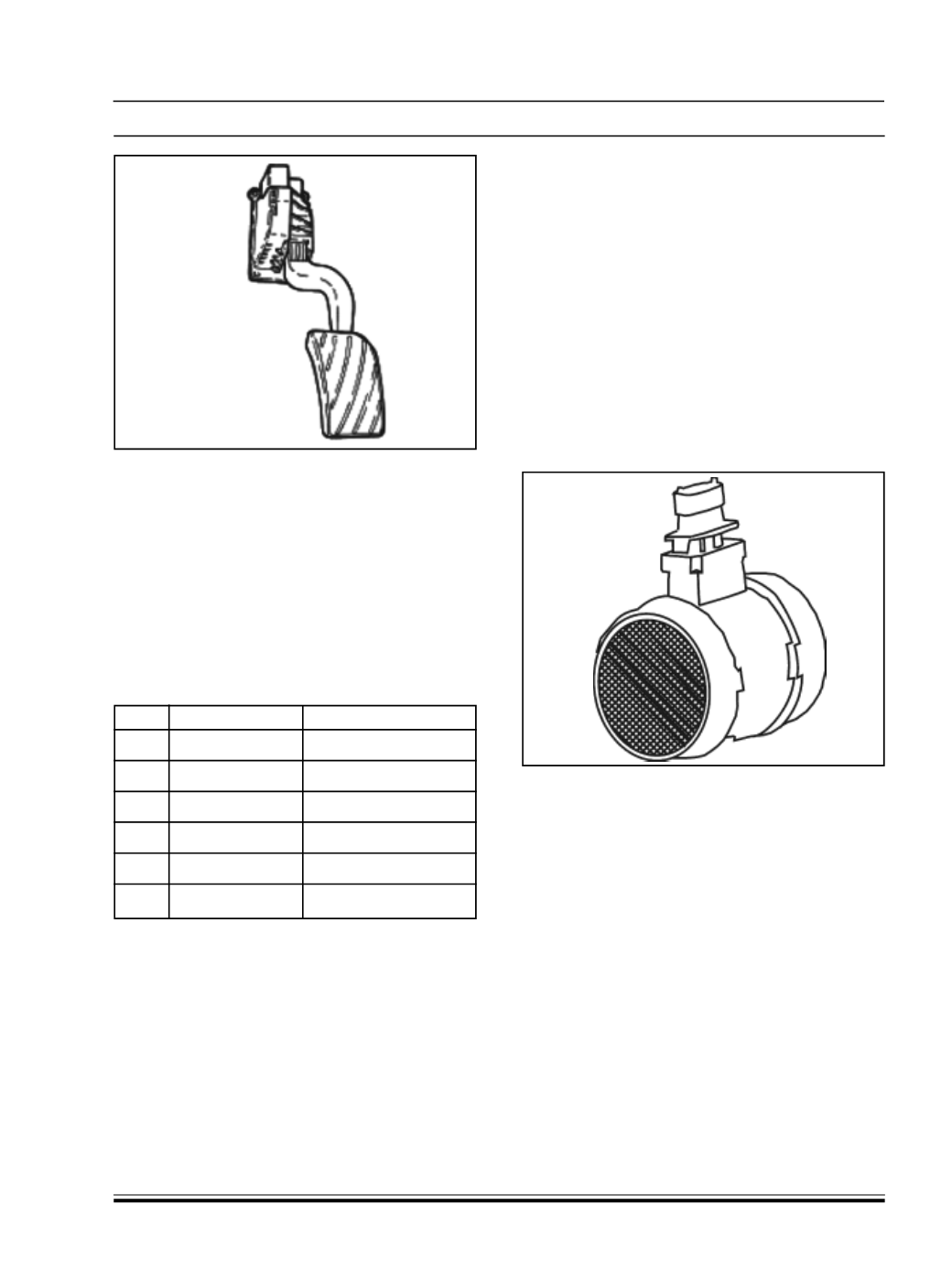
Fig. 183
OPERATION
The accelerator pedal position is converted into an
electrical voltage signal and sent to the injection
control unit by the potentiometer connected to the
pedal.
The accelerator pedal position signal is processed
together with the information relating to the engine
rpm to obtain the injection times and the pressure
PIN OUT
Pin
Description
Signal type
1
Track 2 supply 5 V input
2
Track 1 supply 5 V input
3
Track 1 earth Earth
4
Track 1 signal
Analogue output
5
Track 2 earth Earth
6
Track 2 signal
Analogue output
BOSCH SENSOR TECHNICAL SPECIFICATIONS
Supply voltage: 5 V +/- 0.3 V
Resistance at potentiometer cursor terminals: 1
Kohm +/- 0.4 kOhm
Track 1 resistance: 1.2 Kohm +/- 0.4 kOhm
Track 2 resistance: 1.7 Kohm +/-0.8 kOhm
HELLA SENSOR TECHNICAL SPECIFICATIONS
Supply voltage: 5 V +/- 0.3 V
Resistance at potentiometer cursor terminals: 1
kOhm +/- 0.4 kOhm
Track 1 resistance: 0.9 kOhm +/- 35%....1.4 kOhm
+/- 35%
Track 2 resistance: 1.2 kOhm +/- 35%....2.0 kOhm
+/- 35%.
H. AIR FLOWMETERWITH BUILT INAIR SENSOR
SPECIFICATIONS
The debimeter is located on the air int ake sleeve
and is hot film type.
Fig. 184
The intake air temperature sensor is built into the air
flow meter on the same support as the sensitive
element.