


 294 / 1232

ENGINE 1.3 QUADRAJET (75PS)
69
The fuel feed system consists of:
1. Fuel tank assembly
2. Fuel Intank pump
3. Fuel level gauge (tank unit)
4. Fuel level Indicator (dashboard)
5. Fuel filter
6. Fuel filler cap
7. Fuel hoses, fuel lines and Clamps
8. Assembly filler neck complete
WARNING:
Q
Disconnect negative or positive cable terminal at
battery.
Q
Before performing the following operation, release
the fuel pressure from the fuel system to reduce
the possibility of injury or fire.
Q
While removing the fuel t ank from the vehicle,
keep sparks, cigarettes and open flames away
from it.
Q
Before repairing fuel tank assembly, clean it thor-
oughly.
Q
Always wear safety glasses.
Q
A small amount of fuel may be released during
repair work. To avoid the chance of injury, cover
the pipe to be disconnected with cotton cloth. Do
not use cotton waste.
A. FUEL TANK
The main function of tank is to store fuel and supply
to Engine as per demand. The fuel tank is located
under the rear seat of the vehicle. The fuel level gauge
(Float Assy) is a part of the Intank Pump.
2. Fold rear seat in backward, after that remove the
carpet, it shoes the location of the fuel tank
.
Removal:
1. Remove fuel filler cap.
Warning:
Before removing fuel tank assembly, release the
fuel pressure from the fuel system to reduce the
possibility of injury or fire.
Fuel Pressure Relief procedure:
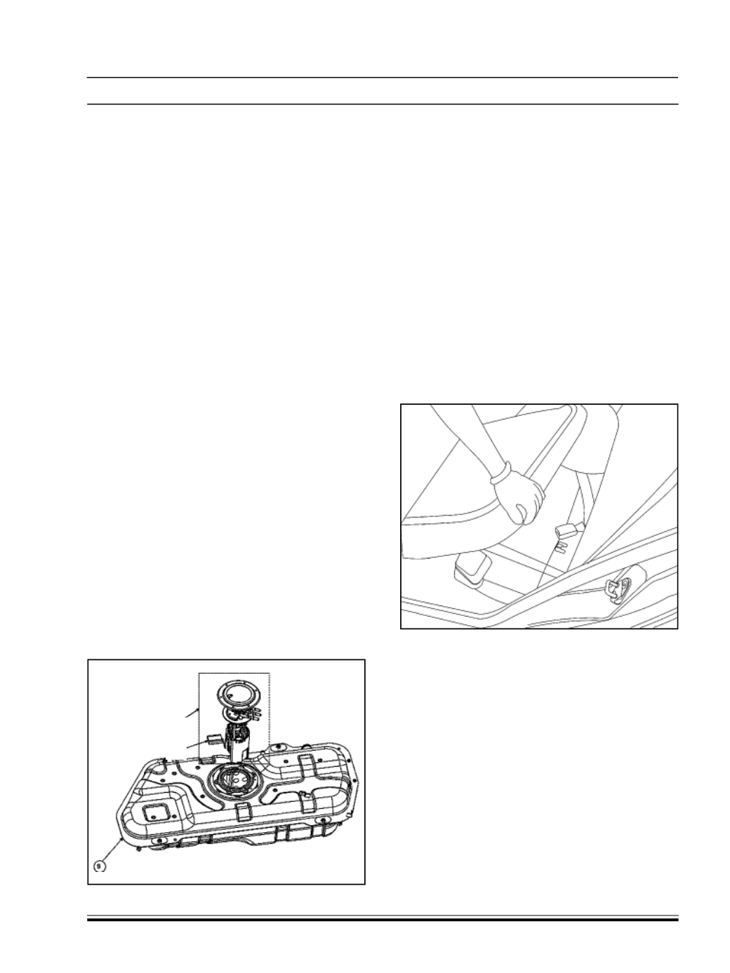
(a) Start the engine, and then disconnect fuel pump
electric connector located under middle floor carpet.
(b) Let engine stall, turn “OFF” ignition switch and then
disconnect negative cable at battery.
(c) Disconnect fuel filler hose and breather hose from
fuel filler Pipe. OR Remove any quick connector using
cotton waste.
Intank fuel pump unit
Float Assy.
REMOVAL OF FUEL TANK UNIT: