


 1092 / 1232

ELECTRICAL
57
12.13
GLOWPLUG CONTROL UNIT
OPERATIONAL DESCRIPTION
The aim of Glow Plug control Unit (GCU) is to
achieve high degree of flexibility in driving the
glow plugs that are included in a standard EMS
system for diesel engines. It is evident that the
requirement for GCU depends from the driving
characteristics required by the glow plugs.
In a modern direct injection diesel engine the
function developed by glow plug may be
summarized as follows:
Auxiliary starting device
Cold diesel engines due to high levels of internal
frictions & thermal losses are reluctant to start.
Often need of auxiliary devices like glow plugs are
the only method to guarantee engine start. The
glow plug power dissipation increases the
combustion chamber temperature allowing the air
fuel mixture to reach its self-ignition condition.
Auxiliary combustion control device
The air fuel mixture self-ignition points are mainly
influenced by two factors: pressure & temperature
inside the combustion chamber. The temperature
control in all those condition in which the
combustion chamber is relatively “cold” (i.e.
during cut-off or during post-start) may improve
the reduction of ignition delay with large benefit in
terms of emission & combustion efficiency.
Auxiliary Power Management device
The total power dissipation of glow plug is not
negligible (it may vary from 240W to 750W
according with glow plug characteristics). In some
cases, it may be useful to increase the engine
load operating point in order to achieve higher
exhaust temperature (e.g. in order to start the
regeneration of diesel particulate filter). The glow
plug activation in this condition may help either
directly, increasing combustion temperature
indirectly increasing engine load as required.
The features of modern Glow plug control unit
must allow the EMS to operate in all of above
conditions with possibility to choose the driving
method & parameter optimization.
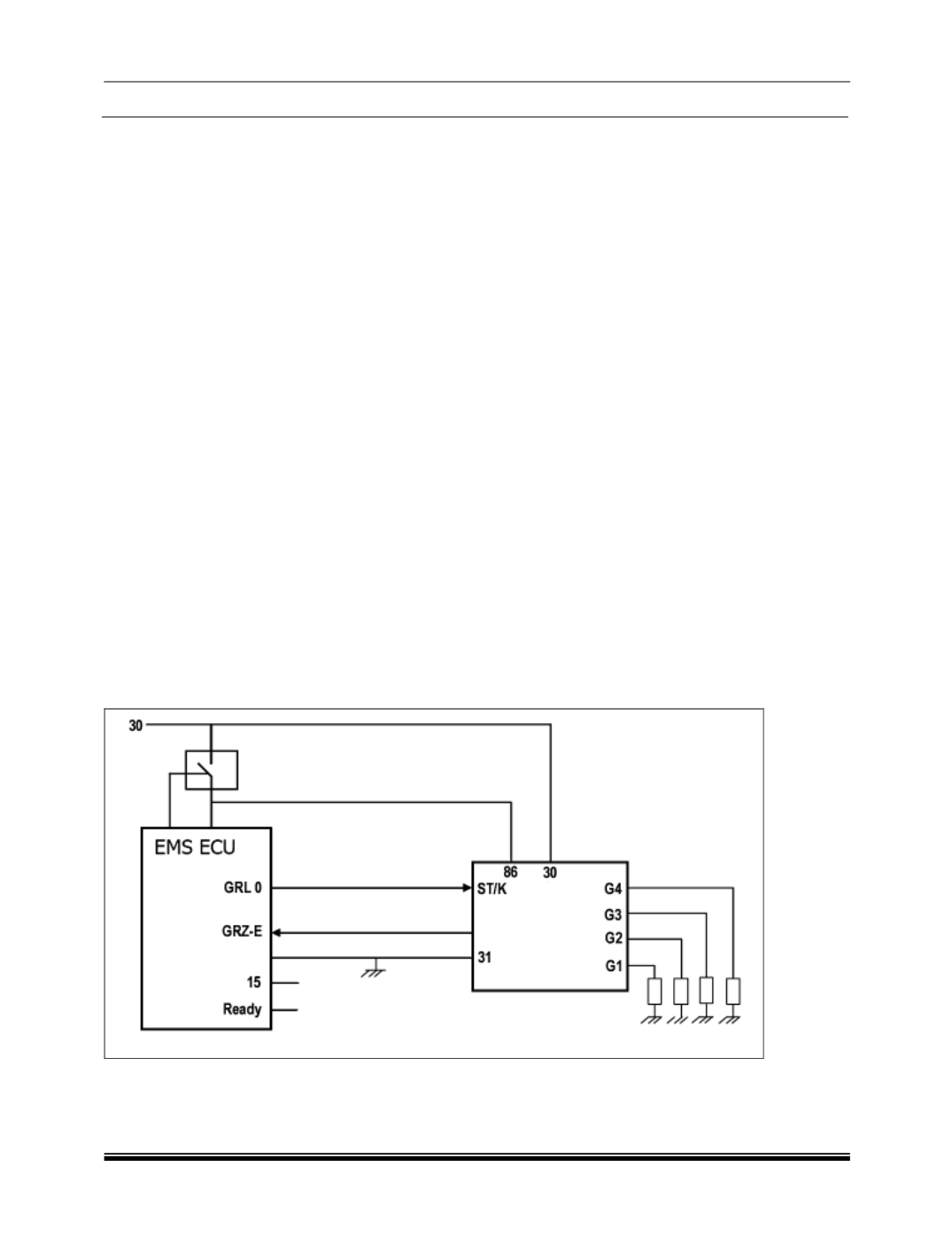
Pin Description:
Pin 30:
Direct battery supply.
G1 :
Power signal for glow plug no.1
G2 :
Power signal for glow plug no.2
G3 :
Power signal for glow plug no.3
G4
: Power signal for glow plug no.4
Pin 86:
Power supply via main relay
ST :
Command signal from ECU to glow plug
controller.
DI :
Diagnostic feedback signal from glow plug
controller to ECU.
Pin 31:
GND