


 327 / 1265

1.5L REVOTORQ ENGINE
72
1.6 ENGINE SYSTEMS
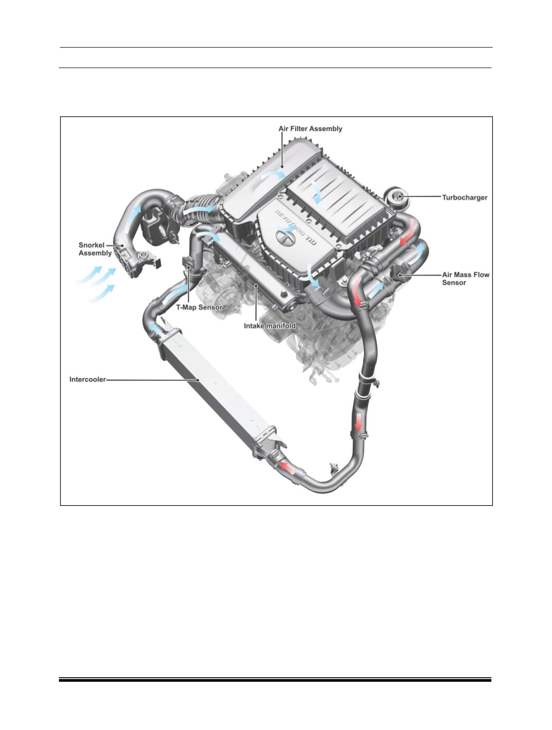
A. AIR INTAKE SYSTEM
Air Intake System Schematic Layout
Description
Air is drawn into the combustion chamber through
the air intake system as shown in above schematic
layout. The air intake system should have the ability
to supply sufficient quantity of air to the engine.
The air is driven to the intake manifold primarily due
to the suction created by the engine. The fresh air
from the outside atmosphere is made to pass
through an air filter and into the VGT (Turbo-
charger). Here the air is compressed by the VGT
which is driven by exhaust gases. It then passes
through the intercooler where it made to dissipate
the heat it has gained by compression and passing
through the VGT which is located on the exhaust
manifold. From here it is drawn into the intake mani-
fold and into the engine.
The Air intake System consists of the following
components.
1. Air Filter.
2. Intake Manifold
3. Intercooler.
4. T-MAP Sensor
5. Air Mass Flow Sensor
6. Snorkel Assembly