


 331 / 561

TIAGO/TIGOR AMT Gasoline
DTC Troubleshooting Guide
Version: 4.0
Date: 18-04-2017
Author: Sathi/Anupama
Page: 197 of 427
Copyright ©
TATA MOTORS Ltd.
This document must not be used in any way, such as copying and redistributing to third parties, without the consent of author.
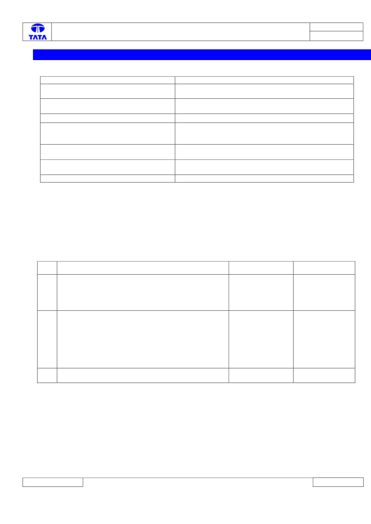
62.
P1889-01: Shift electrovalve – Short to Ground
Overview:
ISO Code
P1889-01
Customer Symptom
Transmission Fault Lamp ON, No gearshifts, Vehicle not
cranking, sudden shift to neutral while driving
Fault Effects (On Vehicle)
No gearshifts, Vehicle not cranking, sudden shift to neutral
while driving, no EOL selftuning
Lamp Status (If Any)
Transmission Fault Lamp ON
Fault Detection Condition
This fault gets detected after Ignition On when shift
electrovalve is commanded ON and a short to ground is
detected on the valve.
Normal Operating Condition
TCU does not detect short to ground
Probable Trouble Area
TCU mountings/ valve body damage / Electro valve / TCU
Healing Condition
50 milliseconds after valid detection of healed condition
Component Details:
The Shift electro valve is a proportional flow control solenoid valve which drives linear motion of the hydraulic shift selection
actuator. This component is mounted on the valve body and makes internal electrical contact with the TCU.
Preliminary Checks:
1) Loose/ Damaged Connections between Electro valve and TCU.
2) Loose/ Damaged mechanical fitments of TCU (TCU to valve body mounting).
3) Check correct fitment of ground cable connections on vehicle chassis.
Trouble Shooting:-
Step Checks
IF YES
IF NO
1
Unmount and remove the TCU from the valve body. Inspect
the condition of the Shift Electrovalve (EV3) (refer fig
below).Check for electrovalve pins damaged/bent/shorting
to other pins. Is the Valve or valve pins visibly
undamaged?
Go to Step 2
Replace the
electrovalve/Valve
Body.
2
Inspect the Shift Electrovalve connector on TCU main
board (refer fig below) for loose fit/disconnection/pin
damage/ short to other pins. Is the Electrovalve connected
properly?
Go to Step 3
Fit the TCU to
valve body back
ensuring proper
contacts.
If TCU side
connector damage
then replace the
TCU.
3
If Problem persists, Replace the valve body and then if still
persists, replace TCU
DTC’s confirmation:-
After rectification, clear all DTC’s and ensure the following points by referring TCU parameters using TML diagnostic tool
before handing over to customer.
Drive the vehicle through all gears in both Automatic and Manual modes
Ensure no DTC is active and Transmission Fault Lamp is OFF.
Circuit Schematic Diagram: