


 332 / 1131

1.5L REVOTORQ ENGINE
77
COMPONENTS
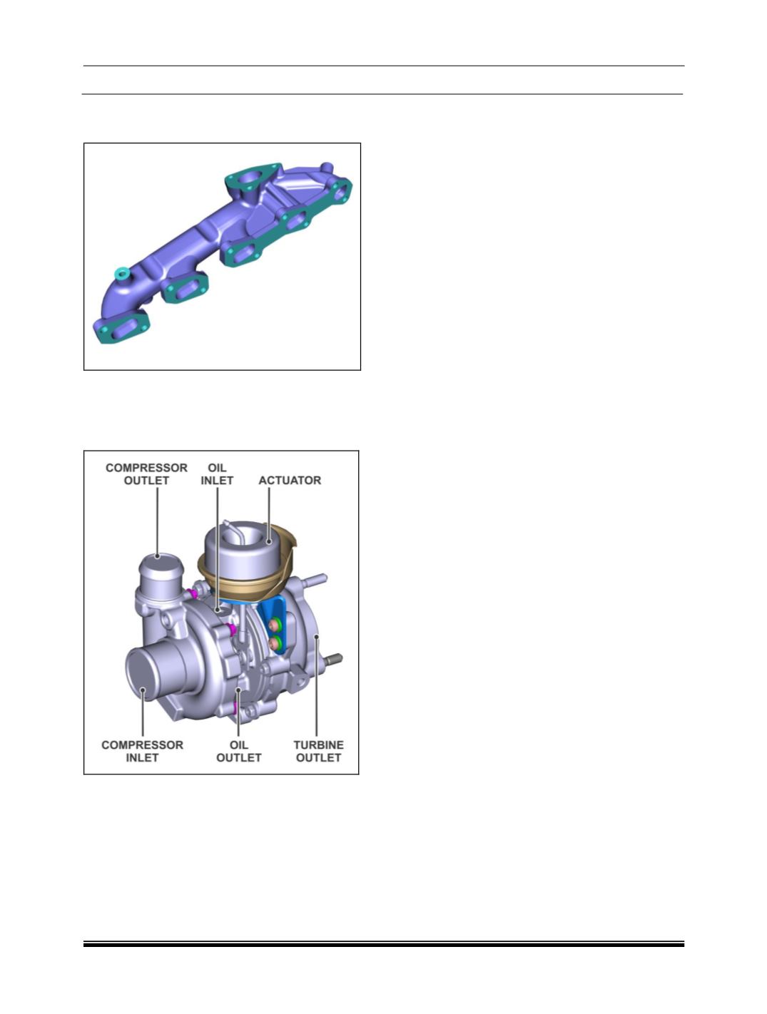
A. Exhaust Manifold
The exhaust manifold is mounted on the cylinder
head. The exhaust gases are trapped out from the
engine through the exhaust manifold.
B. Turbocharger
(VGT)
Compared to traditional turbochargers a Variable
Geometry Turbocharger
(VGT)
has better perfor-
mance at low engine speeds and a low boost
threshold. The geometry of a VGT keeps varying
with engine speed to provide optimum boost. Hence
even at low engine speeds it is able to produce the
required boost.
The actuation for geometry change is controlled by
the EMS ECU instantaneously and progressively.
This gives smooth and better drive ability. The boost
control over the entire speed/load is adjusted such
that it reduces the vehicle emission.
CONSTRUCTION AND FUNCTION
The VGT has a set of movable vanes in the turbine
housing, and they control the boost. At low engine
speeds when exhaust flow is low, the vanes are
partially closed. This increases the pressure of the
exhaust gases pushing against the turbine blades,
making the turbine spin faster and generating more
boost. As engine speed increases, so does the ex-
haust flow, so the vanes are opened to reduce
turbine pressure and hold boost steady or reduce it
as needed. By reading the manifold pressure sen-
sor, the ECU can adjust turbine inlet pressure
(by
varying the Geometry of Vanes)
instantaneously to
control the boost at any speed/ load and to limit
boost at full load.
ADVANTAGES / FEATURES
Good low end torque.
Good transient response.
Good fuel economy.
Increased useful engine operating range.
It provides more matching level of pressure
boost even to a slow spinning turbine without
providing too much of a boost at higher speed.
VGT is electronically controlled and pneumatical-
ly actuated.
Low engine noise.
Lower emission.
SYSTEM FLOW
For system flow schematic refer exhaust system
schematic layout.
The exhaust gases are made to pass through the
turbocharger turbine which will rotate the compres-
sor mounted on the same shaft on the air inlet side.
The air from the air filter is sucked by VGT com-
pressor. The compressed air then flows through an
intercooler and then to the intake manifold. For
more information refer Air intake system.
PRECAUTIONS
Avoid Lifting the turbocharger by holding the ac-
tuator.
Avoid Lifting turbocharger holding the rod end.
Avoid Lifting turbocharger holding the compres-
sor side.
Hold the turbo-charger at the turbine housing
/center housing.