


 484 / 1906

ENGINE
52
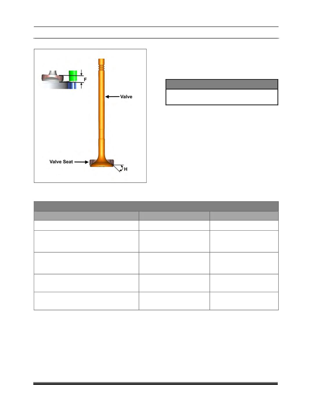
E. Valve Seats :
1. Check valve seat height with respect to
cylinder head mating surface. Replace valve
seat inserts if they are worn out beyond
specified limit.
2. Cut exhaust and inlet valve seats with a
general 45 deg. cutter.
NOTE
Valve seat must be absolutely faultless and
without any chatter marks.
3. If necessary lap the valve seats to a smooth
and even finish by using suitable hand pump
grinder or a lapping paste and valve itself.
4. Smear valve seat with carbon blue. Install
valve in guide and turn it slowly under axial
pressure.
5. Contact line on valve seat must be around
entire circumference at equal width.
6. Distance between narrow diameters of valve
face to contact line should be minimum 0.5
mm.
7. Check for leakages through valve seat by
pouring gasoline on valve head. Gasoline
must not seep past valve seat.
Valve seat Specifications
Dimensions
Intake Valve
Exhaust Valve
Valve Seat Angle 'H'
45
0
+ 15’
45
0
+ 15’
Distance ‘F’ between Cylinder head
mating Surface with crank Case to
Valve Seat in Cylinder head
7.5
- 0.1
mm
7.5
- 0.1
mm
Maximum run out of Valve Seat in
Cylinder Head with Respect to Valve
guide axis
0.1
mm
0.1
mm
Valve Seat Insert Bore Dia. in Cylinder
Head (mm)
Normal : 30.7 H7
Normal 1 : 30.9 H7
Normal : 26.8 H7
Normal 1 : 27 H7
Valve Seat Insert Outside Bore Dia. in
Cylinder Head (mm)
Normal : 30.81 H6
Normal 1 : 31.01 H6
Normal : 26.91 H6
Normal 1 : 27.11 H6