


 421 / 1906

ENGINE
187
PINOUT DETAILS
PIN NO DESCRIPTION
1
EGR +ve input
2
EGR -ve input
3
EGR feed back supply
4
EGR feed back return
5
EGR feed back input
INSPECTION
COLD TEST
Measure the resistance between the two connector
terminals of throttle actuator; it should be ~3 ohms
HOT TEST
1. Apply 13.5V DC to the throttle actuator and
measure the current taken by the actuator, Con-
tinuous current should not be greater than 1.0
Amperes and instantaneous current should not
be greater than 5.5 Amperes.
2. Measure the inductance of the motor coil by
applying 13.5 V AC signal with frequency of 1
KHz.
3. Inductance value should not be greater than 2.3
milli Henry.
REMOVAL
1. Drain the coolant. Refer coolant replacement
procedure in Engine “On Vehicle Repair ‘section
2. Open the bonnet and remove the engine cover.
3. Disconnect the electrical connection of the EGR
valve.
4. Loosen and remove the bolts to disconnect the
EGR pipe from the EGR cooler assembly.
NOTE
The EGR pipe is bent in the intake adaptor pipe and
cannot be removed. Do not attempt to remove it
without the intake adaptor pipe.
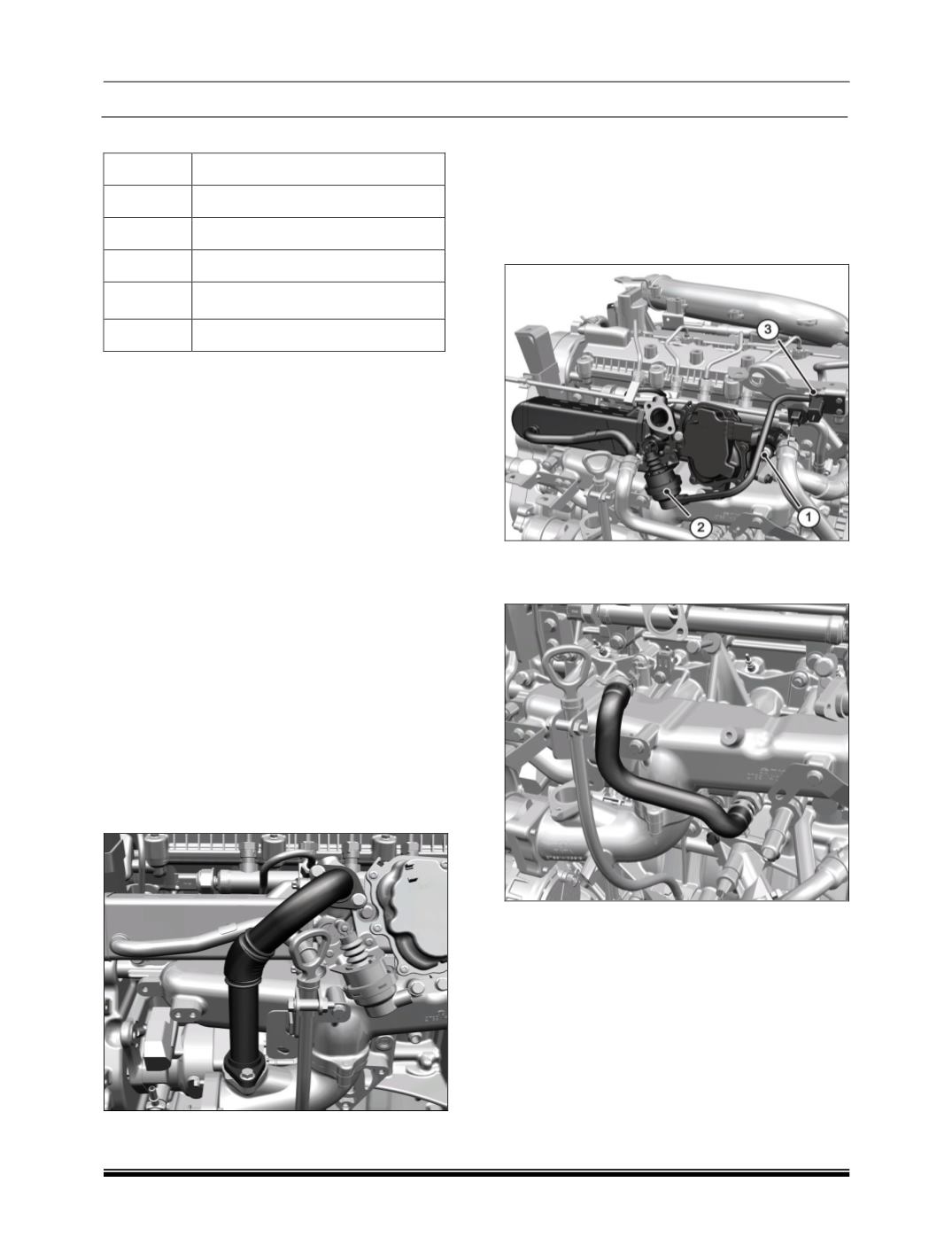
5. Disconnect the hose
(1)
connecting the vacuum
solenoid valve
(3)
to the By-pass actuator valve
(2)
.
6. Remove the spring band clamp
(2)
and discon-
nect the hose
(1)
connecting EGR coolant inlet
to the coolant outlet pipe.