


 212 / 1232

Revotron 1.2T
165
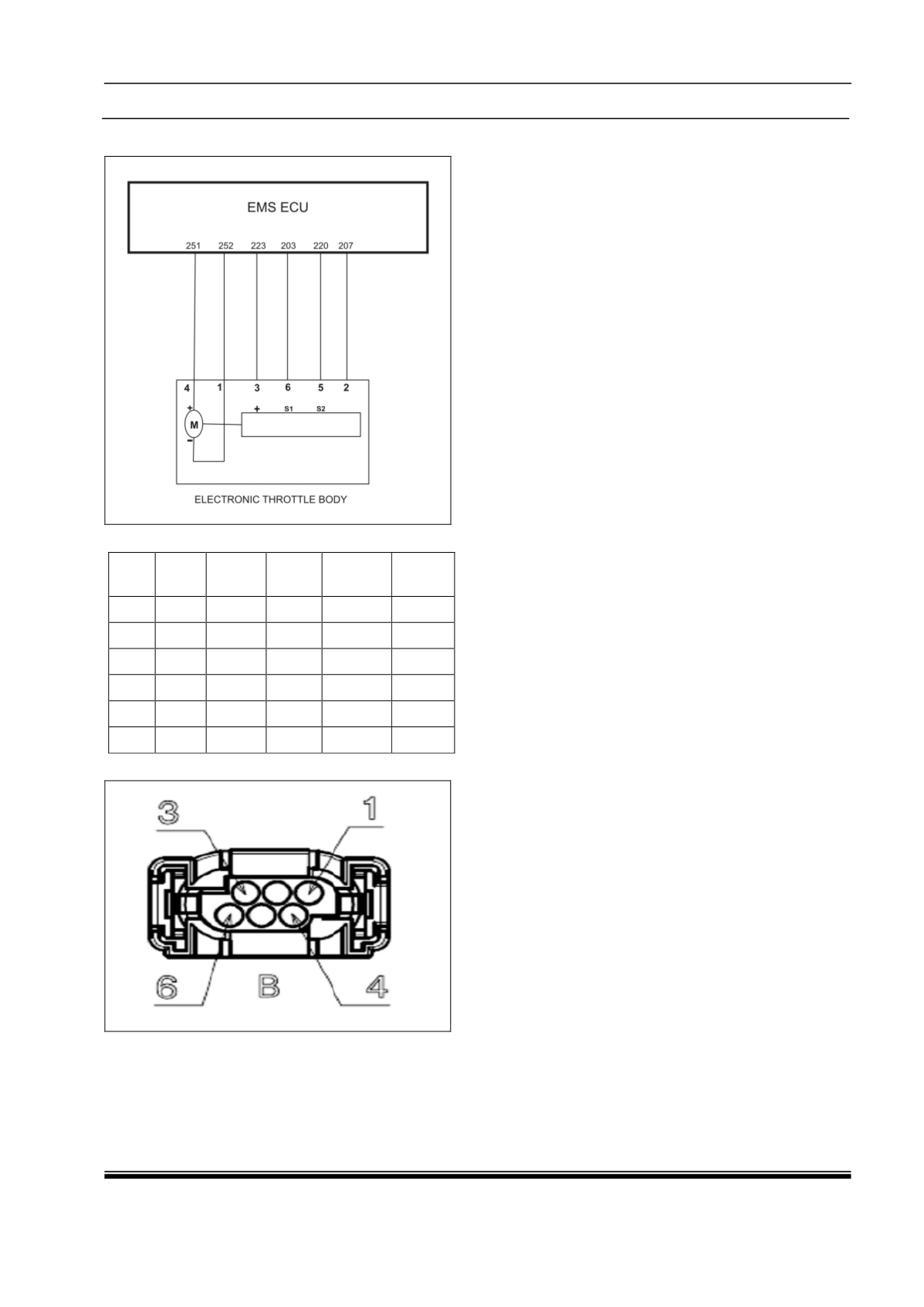
Circuit Schematic Diagram :
Connector Information :
Con
ID
Wire
ID
Color
Size Material Option
1
829
Y/BR
0.75
FLRYB
(AD)
2
825
P/Y
0.75
FLRYB
(AD)
3
828 GY/BR 0.75
FLRYB
(AD)
4
830
V/L
0.75
FLRYB
(AD)
5
826
SB/R
0.75
FLRYB
(AD)
6
827
V/W
0.75
FLRYB
(AD)
Connector View :
Component Specification :
The throttle body contains an actuator, a
throttle plate and a throttle position sensor
(potentiometer), which are integrated into one
housing. The actuator consists of a DC-Motor
and a two-stage gear. The throttle position
sensor is redundant and provides two output
signals. In case of an electrical disconnection,
the throttle plate returns to an idle default
position (LHP) which is between lower and
upper mechanical stops (LMS and UMS,
respectively).
The throttle position sensor is mounted on
intake manifold upstream side and is a part of
integrated throttle body. The TPS is mounted
using a screw and tighten to the specified
torque. The throttle lever is extended to crank
lever which operates the sensor, wherein the
circuit resistance varies depending on the
variation of movement of throttle lever. The
throttle position sensor is a linear
potentiometer type with a two pin connector
blade with integrated 3-way connector.
Depending on the variation of the external
circuit resistance due to movement of the
throttle lever shaft, a fixed DC input
voltage(5V DC) to sensor provides a variable
DC output voltage.
Sensor Stand alone Diagnosis :
With ignition key is 'ON' position and
supply voltage at 5V DC, use multi meter to
measure the signal voltage at pin no. 2 and 3.
Signal Volt = 0.68 V DC at idle position.
Signal Volt = 4.25 ± 0.15V DC at wide
open throttle (WOT) position.
Connector details :
1.
ECU pin M1A3 : Ground
2.
ECU pin M1B4 : Signal
3.
ECU pin M2C3 : 5V supply
Use diagnostic tester to check throttle
sensor by pressing and releasing the
accelerator pedal.
1. Connect variable power supply to the
Throttle Actuator DC Motor pins XX and
XX. Give 5V power supply to Throttle
Position Sensor supply pins xx, xx and
connect ground to sensor ground pins xx,
xx.
2. Vary the supply voltage from 0 to 5 Volts
and check whether the Throttle plate is
moving in counter clockwise direction.
3. Also measure the voltage at the Throttle
position sensor signal pins xx, xx. These
voltage signals should vary according to
the graph shown in above snapshot.