


 109 / 1232

Revotron 1.2T
62
D. Cylinder Head Valve Seats :
1. Check the height of each valve seat insert
with respect to the cylinder head mating
surface. Replace the valve seat if worn
beyond the specified limit.
2. Measure the runout of the valve seat with
respect to the valve guide axis. Maximum
runout is 0.030 mm. Replace or resurface the
valve seat(s) as necessary.
Cylinder Head Vale Seat Resurfacing :
1. If the valve seat is machinable, use a 45
0
cutter to cut the seat to specifications. Use the
appropriate grit to achieve the correct finish
on the seat.
NOTE
•
The valve seat must be free from chatter
marks, scratches and other specifications.
2. Lap the valves and valve seats to a smooth
and even finish using lapping paste and a
hand pump grinder or by inserting the valve
into the cylinder head and rotating to achieve
the proper finish.
3. Coat the valve seat with carbon blue
I
prussian
blue dye and insert the appropriate valve into
the cylinder head.
4. Rotate the valve under axial pressure several
times and remove from the cylinder head.
5. Inspect the area of contact created by the
axial rotation of the valve.
•
The contact pattern should be equal and
unbroken around the circumference of the
seat.
•
The distance from the narrow diameter of
the valve seat face to the contact line
should be0.5 mm.
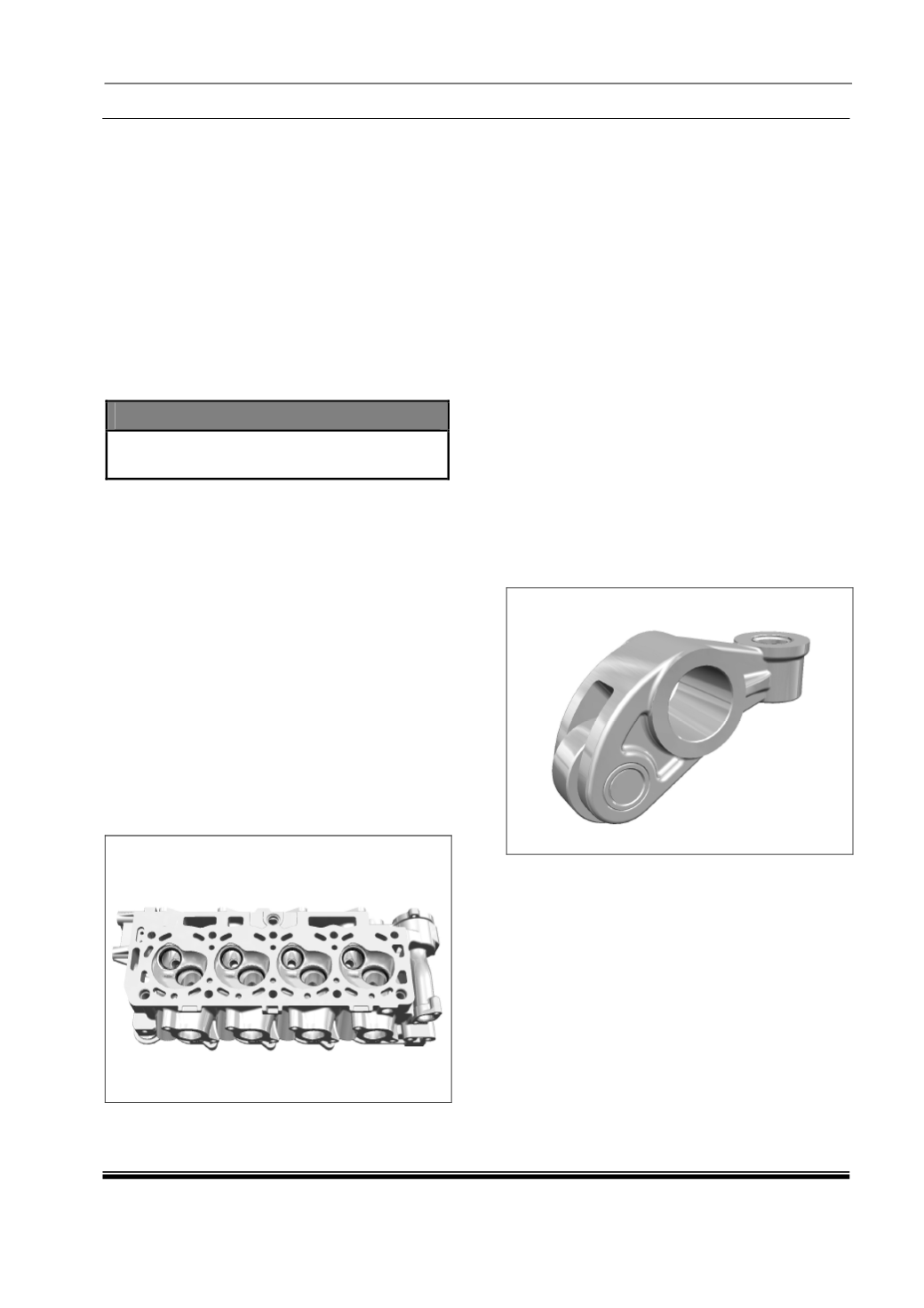
E. Rocker Arms and Shafts :
1. Inspect the bore of each rocker arm for
scoring, signs of excessive heat, cracks or
other damage. Replace the rocker arm as
necessary.
2. Measure the bore of the rocker arm.
The rocker arm bore (I.D.) should be
15.0 +0.011/-0.000 mm. Replace the rocker
arm if outside of these specifications.
3. Inspect the screw adjuster on each rocker for
excessive wear or damage. Replace as
necessary.
4. Inspect both rocker arm shafts for scoring,
signs of excessive heat, cracks or other
damage. Replace the rocker arm shaft as
necessary.
5. Measure the outside diameter (O.D.) along
several points of both rocker arm shafts. The
rocker arm shaft diameter should be
Ø15.0 -0.016/-0.027 mm. Replace the
rocker arm shaft
6. Inspect the rocker arm springs. Replace
springs which are broken, weak, or showing
other signs of damage.